| CPC H02P 21/0007 (2013.01) [H02P 21/18 (2016.02); H02P 25/022 (2013.01); H02P 2207/05 (2013.01)] | 2 Claims |

|
1. A finite time speed control method for a permanent magnet synchronous motor (PMSM) based on a fast integral terminal sliding mode and disturbance estimation, comprising the following steps:
S1: determining a mathematical model of a speed loop of the PMSM under a influence of system parameters uncertainty and unknown load torque;
in a d−q coordinate system, a mathematical model of a speed loop of a non-salient pole permanent magnet synchronous motor is:
 where ω is motor speed; iq represents stator current of q axis; Kt is a torque constant; J represents a moment of inertia; B is a viscous friction coefficient; and TL represents a load torque;
considering the influence of system parameters uncertainty, unknown load torque and current loop tracking error, the mathematical model of the speed loop of the PMSM is:
 in a formula, Bo and Jn represent nominal values of a viscous friction coefficient and the moment of inertia respectively; ΔB=B−Bo and ΔJ=J−Jn represent deviations between true values and the nominal values of the viscous friction coefficient and the moment of inertia; iq* represents a reference value of the stator current of the q axis, a PMSM speed controller to be designed;
after processing the mathematical model of the speed loop of the PMSM which considers the system disturbance, obtaining:
ω=aiq*+d
in the formula, d(t) represents a lumped disturbance term; α is a known constant coefficient;
S2: constructing a fast integral terminal sliding surface:
firstly, defining a speed tracking error: e=ω−ωd, where ωd represents motor target speed;
then, designing the fast integral terminal sliding surface as: s=e+α∫0tedσ+β∫0teq/pdσ; where α, β>0 which are constant coefficients; 0<q/p<1; and q and p are positive odd numbers;
when the tracking error of the motor speed converges to a sliding surface, s=0,
e=−α∫0tedσ−β∫0teq/pdσ;
solving a above equation to obtain time for a tracking error of the motor speed to converge to zero from reaching the sliding surface:
 S3: conducting disturbance estimation on the lumped disturbance term based on an adaptive fuzzy system:
estimating a lumped disturbance term d(t) defined in step S1 by the fuzzy system, and according to a universal approximation theorem of the fuzzy system, an optimal fuzzy system ΦT H(x) exists, so that:
d=ΦTH(x)+ε
in the formula, Φ=[ϕ1,ϕ2, . . . ,ϕr]T is a weight vector at optimal approximation, and r is the number of fuzzy rules; ε represents an estimation error which satisfies |ε|<ρ; ρ>0 is a positive constant; the value of ε can be infinitely reduced by increasing the number of the fuzzy rules; x=[x1,x2, . . . ,xn]T is an input vector of the fuzzy system, and n is the number of fuzzy inputs;
selecting a fast integral terminal sliding surface and a speed tracking error as the inputs of the fuzzy system, x=[s,e]T, with H(x)=[h1(x),h2(x), . . . ,hr((x))]T representing a fuzzy basis function vector, and:
 where μAkl(xk) represents a membership function value of a fuzzy variable;
since a weight vector Φ in optimal approximation cannot be obtained directly, estimating Φ; making Φ represent the estimated value of Φ; and based on an adaptive theory, designing a online adaptive weight adjustment rate of the fuzzy system as:
Φ=ΓH(x)s
where Γ∈Rr×r is a positive definite symmetric matrix; s represents a fast integral terminal sliding surface constructed in step S2;
after obtaining the estimated value Φ of Φ according to the above adaptive weight adjustment rate, using ΦT H(x) to estimate the lumped disturbance term d(t) online;
S4: designing the PMSM speed controller:
designing a following form of PMSM speed controller based on steps S2 and S3:
 in the formula, k1 and k2 are positive adjustable control gains; k2>l+ρ; l>0 is a upper bound of ΦT H(x), |ΦT H(x)|<l; Φ=Φ−Φ represents a weight estimation error vector; and sign(s) represents a signum function;
based on the above PMSM speed controller, making the speed tracking error converge to the sliding surface in time to, with to satisfying a following relational expression:
 in a formula, λ=k2−ρ−l, which represents a constant coefficient; and s(0) represents the value of the fast integral terminal sliding surface s constructed in step S2 at time of 0;
S5: specifically realizing a technical solution:
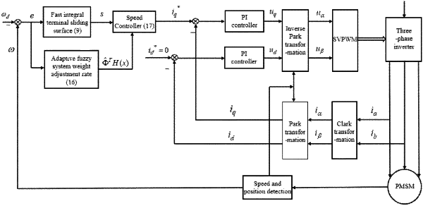
5.1) firstly, measuring the motor speed ω in real time through a sensor installed in the PMSM, and after obtaining a motor speed signal ω, making a difference between the signal and the motor target speed ωd to obtain a speed tracking error e; after obtaining e, further obtaining the value of the fast integral terminal sliding surface s; and meanwhile, based on step S3, obtaining a disturbance estimation value ΦT H(x) outputted by the adaptive fuzzy system;
5.2) secondly, substituting a speed tracking error e, the fast integral terminal sliding surface s and the disturbance estimation value ΦT H(x) into the PMSM speed controller given in step S4, and using the controller as a speed loop controller under a PMSM vector control frame to generate a reference value iq* of stator current of the q axis;
5.3) in a current loop, obtaining a voltage in the d−q coordinate system according to the input stator current reference value using a classical PI controller, obtaining a voltage signal in a static coordinate system through inverse Park transformation, generating a corresponding duty cycle, and obtaining a switch signal of a three-phase inverter; outputting PMSM three-phase stator voltage by the three-phase inverter, and then controlling the motor speed to track the target speed to realize the whole permanent magnet synchronous motor speed regulation process.
|