| CPC H02K 7/003 (2013.01) [B65G 23/22 (2013.01); H02K 1/12 (2013.01); H02K 1/22 (2013.01); H02K 5/04 (2013.01)] | 23 Claims |

|
1. A system, comprising:
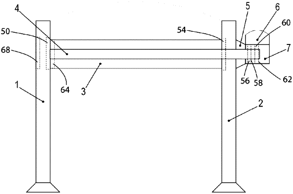
an electric motor including a stator housing and a rotor, the rotor being connected in a torsionally fixed manner to a hollow shaft that is rotatably mounted relative to the stator housing, the hollow shaft being connected in a torsionally fixed and a force-locked manner to a solid shaft that at least partly projects into a recess of the hollow shaft;
wherein the stator housing is connected to a flange that is connected to a second support part on a side facing away from the electric motor;
wherein the solid shaft projects through a recess of the second support part and is rotatably mounted in a first bearing accommodated in a first support part;
wherein the solid shaft is connected to a conveyor device in a torsionally fixed manner, the conveyor device being arranged between the first support part and the second support part;
wherein the flange is connected to the second support part with the aid of screw parts projecting through recesses of the flange and/or with the aid of screws having screw heads projecting through recesses of the flange, each screw part being set apart from the flange, and each respective screw part projecting through a respective spring part that is arranged between the screw part and the flange,
each respective spring part being arranged in a recess that extends axially through the flange; and
wherein the flange is arranged as a truncated pyramid having a square base area.
|