| CPC G06F 1/1656 (2013.01) [G06F 1/1616 (2013.01); G06F 1/1652 (2013.01); G06F 1/1681 (2013.01)] | 12 Claims |

|
1. A support device, wherein the support device is disposed on a back side of a bendable structure, the bendable structure comprising a bending portion, and a first non-bending portion and a second non-bending portion disposed on two sides of the bending portion, respectively; the support device comprising:
a first support, configured to be connected to the first non-bending portion;
a second support, configured to be connected to the second non-bending portion;
a rotating shaft support, configured to be rotatably connected to the first support and the second support; and
at least one support component, wherein each support component is connected to the rotating shaft support and configured to be connected to the bending portion;
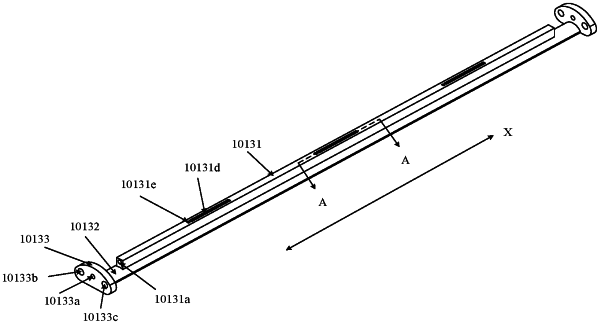
wherein the rotating shaft support comprises a strip-shaped support beam and a strip-shaped rotating shaft; wherein the support beam is provided with a rotating shaft hole penetrating through the support beam, wherein an axis of the rotating shaft hole is parallel to an extending direction of the support beam; and the rotating shaft is disposed in the rotating shaft hole and is rotatable in the rotating shaft hole; and
each support component comprises a strip-shaped support bar, a sheet structure connected to a side of the support bar, and a second protruding structure disposed at an end, distal from the support bar, of the sheet structure; the support beam is provided with a third groove, a fourth groove, and a communication groove disposed inside the support beam and configured to communicate the third groove and the fourth groove; wherein the support bar is disposed in the third groove, the second protruding structure is disposed in the fourth groove, and the sheet structure is disposed in the communication groove; and the support bar is further configured to be fixedly connected to the bending portion.
|