| CPC G02F 1/29 (2013.01) [G02F 1/0322 (2013.01); G02F 1/0311 (2013.01)] | 13 Claims |

|
1. An optical deflection device comprising:
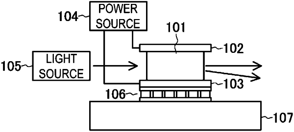
an electro-optic crystal comprising KTa1-xNbxO3, the electro-optic crystal having a first surface and a second surface, the first surface and the second surface facing each other;
a first electrode on the first surface of the electro-optic crystal;
a second electrode on the second surface of the electro-optic crystal;
a power source configured to output a control voltage for forming an electric field inside the electro-optic crystal via the first electrode and the second electrode; and
a light source configured to emit a pulse laser to be incident on the electro-optic crystal along an optical axis, the optical axis substantially perpendicular to a direction of the electric field formed by the control voltage,
wherein a peak power density of the pulse laser output from the light source at a light incidence surface of the electro-optic crystal is less than 800000 W/cm2.
|