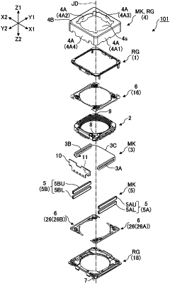
| CPC G02B 7/09 (2013.01) [G02B 27/646 (2013.01); G03B 5/00 (2013.01); G03B 13/36 (2013.01); H02K 11/215 (2016.01); H02K 41/0356 (2013.01); G03B 2205/0007 (2013.01)] | 11 Claims |

|
1. A lens driving apparatus comprising:
a housing including an outer peripheral wall portion and an upper plate portion, the outer peripheral wall portion including a first side plate portion and a second side plate portion facing each other;
a lens holding member positioned in the housing and configured to hold a lens body;
a coil including a wire and held in the lens holding member;
a first magnetic field generating member and a second magnetic field generating member facing each other across the coil and the lens holding member;
a detection magnet held in the lens holding member and configured to detect a position of the lens holding member;
a magnetic detection member disposed so as to face the detection magnet;
a balance magnet held in the lens holding member at a position so as to face the detection magnet across an optical axis of the lens body; and
a first leaf spring and a second leaf spring respectively connected to one end portion and another end portion of the wire, and configured to movably support the lens holding member so as to be movable in a direction of the optical axis, wherein
the detection magnet is disposed at a position closer to the first magnetic field generating member than to the second magnetic field generating member,
the balance magnet is disposed at a position closer to the second magnetic field generating member than to the first magnetic field generating member,
the first magnetic field generating member includes a first inner portion on an inner side facing the lens holding member,
the second magnetic field generating member includes a second inner portion on an inner side facing the lens holding member,
the detection magnet is disposed so as to correspond to the first magnetic field generating member in a direction orthogonal to the direction of the optical axis, and includes a first-detection-magnet portion at one side in the direction of the optical axis and a second-detection-magnet portion at another side in the direction of the optical axis having different magnetic poles from each other,
the balance magnet is disposed so as to correspond to the second magnetic field generating member in the direction orthogonal to the direction of the optical axis, and includes a first-balance-magnet portion at one side in the direction of the optical axis and a second-balance-magnet portion at another side in the direction of the optical axis having different magnetic poles from each other, and
an attraction force is applied between the first inner portion and the first-detection-magnet portion and between the second inner portion and the first-balance-magnet portion, or
a repulsion force is applied between the first inner portion and the first-detection-magnet portion and between the second inner portion and the first-balance-magnet portion.
|