| CPC G02B 6/3817 (2013.01) [G02B 6/3851 (2013.01); G02B 6/3897 (2013.01); G02F 1/133603 (2013.01); G02F 1/133607 (2021.01); H01R 13/46 (2013.01); H01R 13/631 (2013.01); H01R 12/716 (2013.01); H01R 24/60 (2013.01); H05K 1/181 (2013.01); H05K 2201/10189 (2013.01); H05K 2201/10454 (2013.01); H05K 2201/10462 (2013.01)] | 18 Claims |

|
1. A connection system for a printed circuit board, comprising:
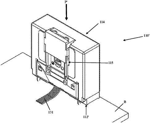
a board-mounted connector comprising a board-mounted connector body configured to mount on the printed circuit board and to hold a plurality of board-mounted optical fibers, the board-mounted optical fibers being operatively connected to the printed circuit board; and
a plug-in connector configured to blind mate with the board-mounted connector, the plug-in connector comprising a plug-in connector body, the plug-in connector further comprising a plug-in ferrule assembly, the plug-in ferrule assembly comprising a plug-in ferrule and a plug- in ferrule holder holding the plug-in ferrule, the plug-in ferrule holder comprising a latch element for latching with the plug-in connector body to retain the plug-in ferrule assembly on the plug-in connector body such that the system makes an optical connection between the plug-in ferrule and the plurality of board-mounted optical fibers when the plug-in connector is blind-mated with the board-mounted connector,
wherein the plug-in ferrule holder comprises a bottom wall and opposing sidewalls, wherein each of the bottom wall and the opposing sidewalls defines a respective blind mating guide,
wherein the latch element comprises a deflectable latch arm with an outwardly projecting latch hook on each of the opposing sidewalls.
|