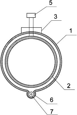
| CPC G01M 3/18 (2013.01) [F17D 5/06 (2013.01)] | 1 Claim |

|
1. An underground leakage-proof pipeline, comprising:
a programmable logic controller (PLC);
an outer pipe;
an inner pipe;
a first water-pressure sensor;
a second water-pressure sensor;
an electromagnetic valve; and
a movable water leakage detection device;
wherein the PLC is arranged on ground; the outer pipe and the inner pipe are both shallowly buried under the ground along a horizontal direction, and the inner pipe is coaxially arranged in the outer pipe; the first water-pressure sensor and the electromagnetic valve are both arranged at a water inlet of the inner pipe, and the second water-pressure sensor is arranged at a water outlet of the inner pipe; the movable water leakage detection device is arranged at a bottom of the outer pipe; the PLC is connected to the first water-pressure sensor, the second water-pressure sensor and the electromagnetic valve respectively through a signal line; and the PLC is connected to the movable water leakage detection device through a control line stored in the outer pipe;
wherein the movable water leakage detection device comprises a conduit, a housing, a micro humidity sensor and a micro-motor; the conduit is parallel to the outer pipe, and is arranged at the bottom of the outer pipe; a top of the conduit is communicated with the bottom of the outer pipe; the housing is arranged in the conduit, and the micro humidity sensor and the micro-motor are both arranged in the housing; the micro humidity sensor is arranged on the micro-motor; a main shaft of the micro-motor is connected to a roller via a gear transmission mechanism, and the roller is configured to roll along the conduit; and the micro humidity sensor and the micro-motor are respectively connected to the PLC through the control line.
|