| CPC G01D 11/30 (2013.01) [F16M 11/247 (2013.01); F16M 2200/08 (2013.01); G01C 5/00 (2013.01)] | 17 Claims |

|
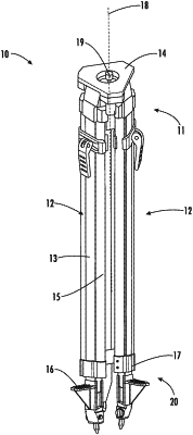
1. A support structure for a laser projection device comprising:
a platform, the platform including a mount configured to securely engage the laser projection device;
a plurality of legs, the plurality of legs including a first end coupled to the platform and a second end opposing the first end;
a longitudinal axis extending through the platform, the plurality of legs arranged around the longitudinal axis; and
a foot coupled to the second end of each of the plurality of legs, each foot comprising:
a foot spike extending along the longitudinal axis;
first and second opposing side surfaces;
a bottom surface extending between and connecting the first and the second opposing side surfaces;
a pin aligned with an axis of rotation, the pin coupled to the foot spike and extending between the first and second opposing side surfaces;
a recess defined in a rear surface of the foot, the recess extending through the bottom surface of the foot; and
a knob coupled to the pin, the knob positioned along one of the first and second opposing side surfaces of the foot;
wherein the pin further includes first and second opposing ends, wherein the first opposing end of the pin is coupled to the knob and the second opposing end of the pin is coupled to a clip;
wherein the foot spike is rotatable about the axis of rotation when the knob is rotated between an extended position in which the foot spike extends beyond the second end of the leg, and a closed position in which the foot spike is located within the foot.
|