| CPC F28D 15/0266 (2013.01) | 3 Claims |

|
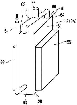
1. An evaporator that evaporates at least a part of a working fluid by heat absorbed from a heat source, comprising:
a housing having a plurality of surfaces including a front surface facing laterally and a top surface facing upward, and storing the working fluid; and
a heat absorber disposed on the front surface, including radiating fins projecting into the housing, and being thermally connected to the heat source, the heat absorber absorbs heat from the heat source and releases it to the working fluid through the radiating fins,
wherein:
the housing includes: at least one working fluid inlet located in a surface of the housing, the surface being other than the top surface of the housing; and at least one pair of working fluid outlets located respectively in opposite longitudinal end portions of the top surface,
when the top surface of the housing is positioned horizontally, a boundary plane at which a volume ratio of gas in two-phase flow is 50% is located below the working fluid outlets and above the heat absorber,
the top surface of the housing is quadrilateral, and the working fluid outlets are located at diagonally opposite corners of the top surface of the housing, and
one of the working fluid outlets is closer to the front face of the housing than another of the working fluid outlets.
|