| CPC F24F 11/75 (2018.01) [F16K 1/22 (2013.01); F24F 13/1426 (2013.01); G05D 7/0173 (2013.01)] | 20 Claims |

|
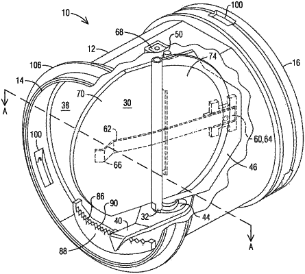
1. An automatic airflow balancing valve comprising:
a housing comprising an inlet and an outlet and defining a flow path within the housing from the inlet to the outlet;
an adjustment plate disposed within the flow path and configured to rotate, about an adjustment plate axis, within the flow path;
an adjustment element coupled to the adjustment plate and configured to secure the adjustment plate in any of a plurality of selectable rotational positions, wherein each of the selectable rotational positions corresponds to a different flow rate, and wherein the adjustment element includes a slot defined therein that is spaced apart from the adjustment plate axis; and
a valve disc operatively connected to the housing and disposed within the flow path, wherein the valve disc:
is configured to rotate, about a valve disc axis, within the flow path, wherein the valve disc axis extends into the slot and is movable with respect to the slot to different positions along the slot,
is biased to a rotational position of the adjustment plate, and
comprises a first portion extending from the valve disc axis toward the inlet and a second portion extending from the valve disc axis toward the outlet.
|