| CPC F16K 17/04 (2013.01) [F16K 27/0209 (2013.01); F04C 14/24 (2013.01)] | 8 Claims |

|
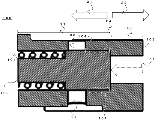
1. A relief valve, switching between whether to discharge oil through movement of a valve body, the relief valve comprising:
a first spacing part, in which the valve body moves;
a second space part, connected with the first space part and having a diameter smaller than a diameter of the first space part;
an elastic body, connected with the valve body;
a seal part, disposed in a circumferential direction of the valve body; and
a third space part, formed in the first space part,
wherein the first space part and the second space part are connected at a first end of the first space part, and
the seal part is disposed at a position that is a side surface with respect to a first surface formed on a side of the first end, among surfaces which the valve body has, in a vertical direction with respect to a direction in which the valve body moves reciprocally, and extends from the third space part to a boundary between the first space part and the second part.
|