| CPC F16H 15/38 (2013.01) [F16H 57/043 (2013.01); F16H 57/0471 (2013.01); F16H 57/049 (2013.01)] | 11 Claims |

|
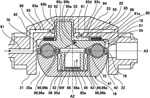
1. A toroidal continuously variable transmission comprising:
an input disc and an output disc arranged so as to be opposed to each other;
a power roller that is sandwiched between the input disc and the output disc so as to be tiltable and transmits rotational driving force of the input disc to the output disc at a change gear ratio corresponding to a tilt angle of the power roller;
a trunnion that is tiltable about a tilt axis of the power roller;
a support that is arranged between the trunnion and the power roller in a direction along a rotation axis of the power roller and supports the power roller such that the power roller is rotatable relative to the trunnion about the rotation axis;
a thrust bearing that receives a load of the rotating power roller in the direction along the rotation axis; and
an oil passage through which lubricating oil is supplied to the thrust bearing, wherein:
an opposing surface of the support which surface is opposed to the power roller includes a first bearing groove having an annular shape about the rotation axis;
an opposing surface of the power roller which surface is opposed to the support includes a second bearing groove that is opposed to the first bearing groove and has an annular shape about the rotation axis;
the thrust bearing includes
rolling elements held by the first bearing groove and the second bearing groove so as to be rollable and
an annular retainer arranged between the power roller and the support and including retaining holes that hold the rolling elements;
the oil passage includes nozzles that are located at a radially inner side of the retainer and define a flow direction of the lubricating oil flowing toward the thrust bearing, each of virtual axes of discharge ports of the nozzles extending in the flow direction of the nozzle and reaching the first bearing groove;
the support including the first bearing groove includes an inner groove shoulder portion that is a portion located at a radially inner side of the first bearing groove;
regarding each of the virtual axes, when viewed from a direction which is perpendicular to the virtual axis and the direction along the rotation axis, the inner groove shoulder portion and an inner peripheral portion of the retainer which is a portion located at a radially inner side of the retaining holes are located at respective sides opposite to each other across the virtual axis and away from the virtual axis; and
one or each of the inner groove shoulder portion and the inner peripheral portion includes an inclined surface that is inclined along the flow direction of the nozzle relative to a plane perpendicular to the direction along the rotation axis.
|