| CPC F01N 3/2892 (2013.01) [F01N 3/033 (2013.01); F01N 3/035 (2013.01); F01N 3/037 (2013.01); F01N 3/24 (2013.01); F01N 13/009 (2014.06); F01N 2330/38 (2013.01); F01N 2470/30 (2013.01); F01N 2560/026 (2013.01); F01N 2590/08 (2013.01); Y02A 50/20 (2018.01)] | 7 Claims |

|
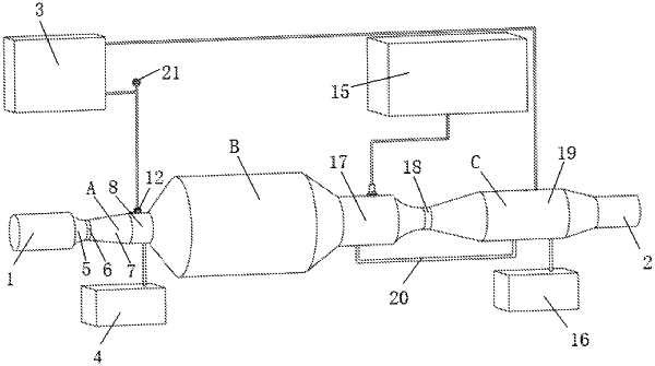
1. A swirl structure-based exhaust aftertreatment device for an underground mining diesel vehicle, comprising a water tank (3), a PM collection tank (4), an inlet tube (1), a high-speed rotary exhaust separator (A), an exhaust catalytic converter (B), a circulating NOx selective catalytic reduction system (C) and an exhaust tube (2), wherein the inlet tube (1), the high-speed rotary exhaust separator (A), the exhaust catalytic converter (B), the circulating NOx selective catalytic reduction system (C) and the exhaust tube (2) are sequentially connected from front to back;
the high-speed rotary exhaust separator (A) comprises a Laval tube (5), a throat tube (6), a swirl tube (7) and a first deposition tube (8) which are sequentially connected from front to back, the Laval tube (5) is a constricted section, the swirl tube (7) is an expanded section, the Laval tube (5) is connected to the inlet tube (1), and the first deposition tube (8) is connected to the water tank (3) through a first pipeline and is connected to the PM collection tank (4) through a second pipeline; an overflow tube (9) for connecting the Laval tube (5) and the swirl tube (7) is mounted in the throat tube (6), an internal swirl unit (10) and an external swirl unit (11) which are as long as the swirl tube (7) are mounted in the swirl tube (7), and a front end of the internal swirl unit (10) is inserted into the overflow tube (9); automatic flow control valves (12) are arranged on the first pipeline and the second pipeline respectively, a sprayer is mounted at a tail end of the first pipeline, and a pressure sensor is arranged on the first deposition tube (8) and is used for feeding back a signal to control the automatic flow control valves (12);
wavy ducts (13) and straight ducts (14) are arranged in the exhaust catalytic converter (B); all ducts below a central axis are wavy ducts (13), front ends of the ducts are open, and tail ends of the ducts are closed; ducts above the central axis are wavy ducts (13) and straight ducts (14), front ends of the dusts are closed, tail ends of the ducts are open, and the straight ducts (14) are arranged along an inner wall of the exhaust catalytic converter (B); the ducts below the central axis are connected at peaks, the wavy ducts above the central axis are connected at peaks and are connected to the straight ducts at corresponding positions, the two ducts adjacent to the central axis are connected, peaks of the adjacent ducts on the central axis are connected to troughs of the adjacent ducts below the central axis, and inner walls of all the ducts are coated with a perovskite catalyst;
the circulating NOx selective catalytic reduction system (C) comprises an NH3 storage tank (15), an NH3 recycling tank (16), a multi-component mixing tube (17), a swirl reactor (18) and a second deposition tube (19), wherein the multi-component mixing tube (17), the swirl reactor (18) and the second deposition tube (19) are sequentially connected from front to back, the multi-component mixing tube (17) is connected to the second deposition tube (19) through a return tube (20), the second deposition tube (19) is connected to the water tank (3) through a third pipeline and is connected to the NH3 recycling tank (16) through a fourth pipeline, the NH3 storage tank (15) is connected to the multi-component mixing tube (17) through a fifth pipeline, an electric damper is arranged in the vicinity of a tail end of an interior of the second deposition tube (19), automatic flow control valves (12) are arranged on the third pipeline, the fourth pipeline and the fifth pipeline respectively, and sprayers are mounted at tail ends of the third pipeline and the fifth pipeline; an NOx sensor for monitoring a concentration of NOx and a pressure sensor for monitoring an internal pressure and a spraying pressure of NH3 are arranged on the multi-component mixing tube (17), and an NOx sensor for monitoring the concentration of NOx, an NH3 sensor for monitoring the concentration of NH3, and a pressure sensor for feeding back a signal to control the electric damper and the corresponding automatic flow control valves (12) are arranged on the second deposition tube (19).
|