| CPC E02B 7/28 (2013.01) [E02B 7/30 (2013.01); E02B 7/36 (2013.01); E02B 7/54 (2013.01); E02B 8/00 (2013.01); G01N 35/00 (2013.01)] | 11 Claims |

|
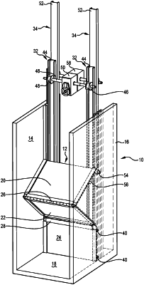
1. A control gate adapted to be installed across a channel for liquids, the control gate comprising:
at least two panels hingedly connected together, said panels having opposing sides for sealing engagement with side walls of said channel, a lowermost panel of the at least two panels being positioned for sealing engagement with a floor of said channel, and wherein said at least two panels are substantially vertically aligned in a fully closed position of said control gate;
at least one first lifting device connected to a top of an uppermost panel of the at least two panels and adapted to lower and raise said uppermost panel relative to its hinged connection in a concertina manner to set an overshot position for said control gate; and
at least one second lifting device connected to a bottom of the lowermost panel to raise and lower said lowermost panel from said floor of said channel to set an undershot position for said control gate;
said first and second lifting devices comprising a cable drive having a linear drive member, a cable drum having an axle to allow rotation of said cable drum, said cable drum having a cable affixed at one end of the cable to said linear drive member and at the other end of said cable to a respective panel, said cable being tautly wrapped around said cable drum, said cable drum located between ends of said linear drive member to, in use, allow said linear drive member to move when said axle is rotated and thus raise or lower said respective panel and; and
said side walls include a pair of parallel grooves on an inside of said channel, a pair of the first lifting devices connected to respective ends of the top of said uppermost panel, a respective first roller attached to said respective ends of the top of said uppermost panel and located within one of said parallel grooves, said lowermost panel having a pair of the second lifting devices connected to respective ends on a rear face of said lowermost panel, a respective second roller attached to said respective ends on the rear face of said lowermost panel and located within the other of said parallel grooves.
|