| CPC C23C 16/45565 (2013.01) [C23C 16/4557 (2013.01); C23C 16/45572 (2013.01); H01J 37/3244 (2013.01); H01J 37/32449 (2013.01); H01J 2237/3321 (2013.01)] | 11 Claims |

|
1. A method for heat treating a substrate (9) in a chemical vapor deposition (CVD) reactor, the method comprising:
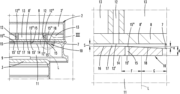
using a susceptor (3) and a shield plate (10) in a process chamber (11) of the CVD reactor,
wherein a radially outermost edge of the susceptor (3) defines a cylindrical shell surface boundary (L),
wherein a gas inlet member (2) has a first circular outline and a ceiling panel (8) facing towards the process chamber (11), and
wherein the ceiling panel (8) has outlet openings (12′),
placing the substrate (9) on the susceptor (3);
heating the susceptor (3) with a heating device (4) and cooling the ceiling panel (8) so as to generate a heat flow from the susceptor (3) to the ceiling panel (8),
wherein the shield plate (10) has a second circular outline, a central zone, an annular zone (18) surrounding the central zone, a rear face (16) facing towards the ceiling panel (8), and a first gas outlet surface (14),
wherein the first gas outlet surface (14) is planar,
wherein the rear face (16) in the central zone defines a rear plane extending parallel to the first gas outlet surface (14),
wherein in the annular zone (18), a material thickness (d) of the shield plate (10) continuously decreases in a radial direction pointing away from a center of the shield plate (10),
wherein the shield plate (10) is located adjacent to the ceiling panel (8) such that the first gas outlet surface (14) faces towards the process chamber (11) into which gas passageways (15) of the shield plate (10) lead,
wherein the shield plate (10) is spaced apart from a second gas outlet surface (8′) formed by the ceiling panel (8) by a gap (17), and
wherein the cylindrical shell surface boundary (L) intersects the annular zone (18) such that a radially inner region (F) of the annular zone (18) extends radially inwards from the cylindrical shell surface boundary (L) towards the center of the shield plate (10).
|