| CPC B66D 1/36 (2013.01) [A45F 5/004 (2013.01); B65H 75/406 (2013.01); B65H 75/4471 (2013.01); B65H 75/486 (2013.01); B66D 1/02 (2013.01)] | 17 Claims |

|
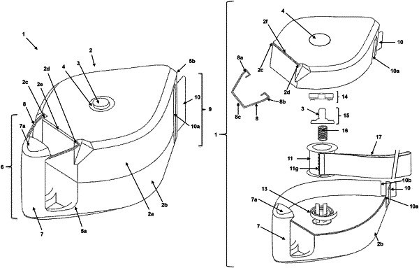
1. A lanyard attachment, comprising:
a housing with a front portion and a back portion;
a rotatable spool disposed within the housing and releasably storing the lanyard in a coiled configuration, comprising:
a first cavity with a first exteriorly flanged edge formed thereon in communication with an aperture on the front portion and containing the manually controllable button assembly therein;
a second cavity with a second exteriorly flanged edge formed opposite to said first cavity and containing a torsion spring therein in operable contact with the rotatable spool; and
an attachment bar fastened between the first exteriorly flanged edge and the second exteriorly flanged edge of the spool to which both ends of the lanyard are attached;
a manually controllable release assembly disposed through an aperture on the front portion of the housing in operable contact with the rotatable spool;
a guide formed across a proximal end of both of the front portion and the back portion to guide the lanyard into the housing; and
a holder disposed at a distal end of the housing from which an object is removably suspendable.
|