| CPC B65H 31/22 (2013.01) [B65H 31/02 (2013.01); G03G 21/1619 (2013.01); B65H 2301/4212 (2013.01); B65H 2402/10 (2013.01); B65H 2402/32 (2013.01); B65H 2402/40 (2013.01); B65H 2402/441 (2013.01); B65H 2601/324 (2013.01); B65H 2601/61 (2013.01); B65H 2801/06 (2013.01)] | 16 Claims |

|
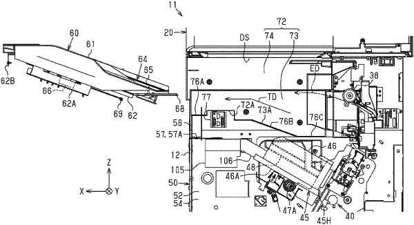
1. A multifunction machine comprising: when in a Z axis orthogonal to an installation surface of the multifunction machine, a multifunction machine side with respect to the installation surface is defined as a +Z direction and an opposite side is defined as a −Z direction,
a main body frame having a first frame and a second frame which respectively have surfaces parallel to the Z-axis and face each other;
a recording head disposed between the first frame and the second frame and supported by the main body frame;
an ejection tray which is fixed to the main body frame on the +Z direction with respect to the recording head and on which a medium ejected after being recorded by the recording head is placed; and
a scanner fixed to the main body frame on the +Z direction with respect to the ejection tray and forming an ejection space with the ejection tray, wherein
the ejection tray is configured to be removed toward a second direction, which is an in-plane direction of the first frame, in a state where the scanner is fixed to the main body frame, and
the recording head is configured to be removed toward a third direction, which is the in-plane direction of the first frame, in a state where the scanner is fixed to the main body frame after the ejection tray is removed.
|