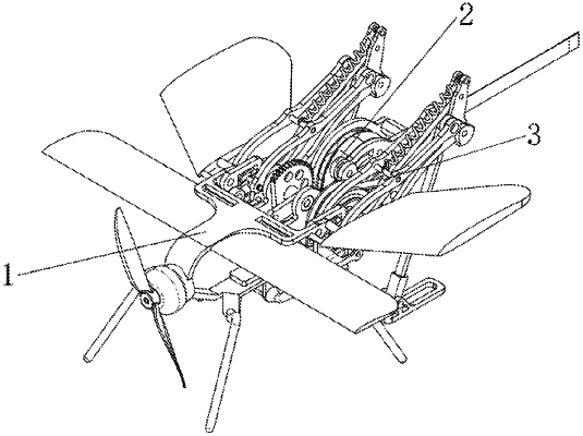
| CPC B64C 39/003 (2013.01) [B62D 57/02 (2013.01); B62D 57/04 (2013.01); B64C 3/38 (2013.01); B64C 3/385 (2013.01); B64C 11/00 (2013.01); B64C 25/62 (2013.01); B64C 39/08 (2013.01); B64D 27/24 (2013.01); B64U 10/20 (2023.01); B64U 60/50 (2023.01); B64U 60/55 (2023.01); B64C 2025/008 (2013.01)] | 1 Claim |

|
1. A jumping and flying robot having a shape of an insect, wherein the robot comprises
a flying module comprising
a propeller,
a miniature model airplane motor,
front wings,
rear wings, and
a supporting frame;
wherein the propeller is mounted on the miniature model airplane motor; the miniature model airplane motor is mounted on a front end of the supporting frame; the front wings and the rear wings are mounted on the supporting frame through a first shafting and are configured to rotate around their respective mounting shafts of the first shafting;
a driving module comprising
a brushless motor,
a gear fixed plate,
a motor fixed plate,
a synchronous wheel fixed plate,
a synchronous wheel set,
a gear set,
a driving push rod, and
a body connecting plate;
wherein the brushless motor is fixed on the motor fixed plate via first screws, the synchronous wheel set comprises a first synchronous wheel, a second synchronous wheel and a synchronous belt, the first synchronous wheel is mounted on an output shaft of the brushless motor, the second synchronous wheel is mounted on the synchronous wheel fixed plate via a first bearing, the first synchronous wheel is in transmission connection with the second synchronous wheel by the synchronous belt; the gear set comprises a first gear and a second gear, the first gear is fixedly connected with an extension shaft of the second synchronous wheel; the second gear is fixed to the gear fixed plate via a second bearing, and the first gear is meshed with the second gear; the gear fixed plate, the motor fixed plate, and the synchronous wheel fixed plate are connected to the body connecting plate via second screws; a front end of the body connecting plate is connected to the supporting frame, and another two ends of the body connecting plate are symmetrically installed with biomimetic bouncing legs; the driving push rod is fixedly connected with the second gear to act on the biomimetic bouncing legs; and
biomimetic bouncing legs, each comprising
a femur driving rod,
a first connecting rod of a femur upper X-shaped rod group,
a second connecting rod of the femur upper X-shaped rod group,
a femur lower connecting rod,
a knee joint,
a tibia connecting rod,
a leg fixed bracket,
a tarsus, and
a force accumulating spring;
wherein the femur driving rod is connected to a shaft hole on an upper side of the leg fixed bracket via a second shafting and is fixed via a first circlip; the first connecting rod of the femur upper X-shaped rod group is connected with a first end of the femur driving rod via a third shafting and is fixed via a second circlip; the second connecting rod of the femur upper X-shaped rod group is connected with a second end of the femur driving rod via a third screw; a first end of the femur lower connecting rod is connected with a shaft hole on a lower side of the leg fixed bracket, and a second end of the femur lower connecting rod is provided with two shaft holes respectively connected to the first connecting rod of the femur upper X-shaped rod group and the knee joint; the knee joint is provided with mounting holes, a first end of the force accumulating spring, the second connecting rod, the femur lower connecting rod, and the tibia connecting rod are separately connected with the mounting holes from up to down; a tip end of the tibia connecting rod and the tarsus are connected via a fourth shafting and fixed via a third circlip; the first end of the force accumulating spring is connected to the knee joint, and a second end of the force accumulating spring is connected to a mounting hole on the first connecting rod.
|