| CPC B29C 45/842 (2013.01) [B29C 45/14 (2013.01); B29C 45/2675 (2013.01); B29C 45/80 (2013.01); B29D 11/00951 (2013.01); G02B 21/0016 (2013.01); B29C 2945/76096 (2013.01); B29C 2945/76294 (2013.01); B29C 2945/76461 (2013.01); B29C 2945/76943 (2013.01); B29D 11/0048 (2013.01); B29L 2011/0041 (2013.01)] | 11 Claims |

|
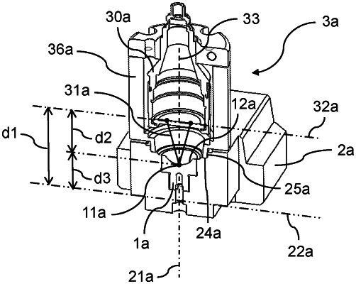
1. A method for verifying whether a molding insert (1a, 1b) is accurately mounted to a tooling plate (2a, 2b) of an injection-molding apparatus for molding ophthalmic lens molds, the tooling plate (2a, 2b) having a mounting axis (21a, 21b) for the molding insert (1a, 1b), the method comprising the steps of:
a) providing a confocal sensor (3a, 3b) having a measurement beam (31a, 31b);
b) arranging the confocal sensor (3a, 3b) relative to the tooling plate (2a, 2b) such that a reference plane (32a, 32b) of the confocal sensor (3a, 3b) as well as a reference plane (22a, 22b) of the tooling plate (2a, 2b) are normal to the mounting axis (21a, 21b), with the reference plane (32a, 32b) of the confocal sensor (3a, 3b) being spaced from the reference plane (22a, 22b) of the tooling plate (2a, 2b) by a predetermined first distance (d1, e1);
c) with the aid of the measurement beam (31a, 31b) of the confocal sensor (3a, 3b), measuring a second distance (d2, e2) between the reference plane (32a, 32b) of the confocal sensor (3a, 3b) and a central impingement location (11a, 11b) of the measurement beam (31a, 31b) on a molding surface (12a, 12b) of the molding insert (1a, 1b);
d) based on the measured second distance (d2, e2) as well as based on the predetermined first distance (d1, e1), determining a third distance (d3, e3) of the central impingement location (11a, 11b) on the molding surface (12a, 12b) of the molding insert (1a, 1b) relative to the reference plane (22a, 22b) of the tooling plate (2a, 2b);
e) comparing the determined third distance (d3, e3) with a predetermined target distance, and
f) determining that the molding insert (1a, 1b) is accurately mounted to the tooling plate (2a, 2b) if the difference between the determined third distance (d3, e3) and the predetermined target distance is less than a predetermined threshold difference.
|