| CPC B26B 25/002 (2013.01) [A22B 5/165 (2013.01); A22C 17/12 (2013.01); B25F 5/02 (2013.01)] | 20 Claims |

|
1. A split blade housing assembly for a power operated rotary knife, the split blade housing assembly comprising:
a split blade housing including an annular blade support section and a mounting section extending from the annular blade support section, the mounting section including a split through the mounting section and a first body portion and a second body portion on opposite sides of the split; and
a cam mechanism bridging the split through a mounting section of the split blade housing for moving the split blade housing between a first blade supporting position and a second blade changing position, the cam mechanism including:
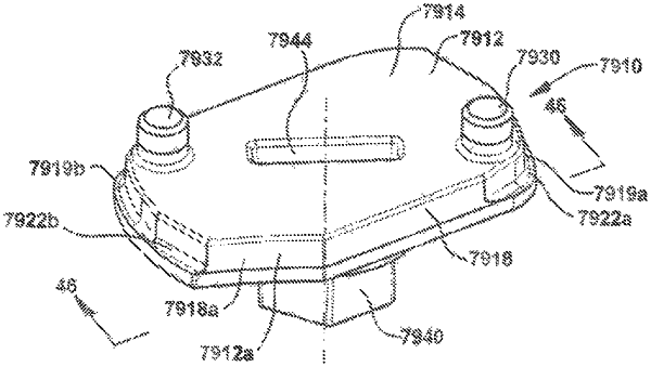
a cam plate including a first surface and a second surface spaced apart by a front side, a back side and first and second lateral sides extending between the first and second surfaces, the first surface of the cam plate including a recess, the first surface of the cam plate adjacent the first and second lateral sides including first and second extending edges extending upwardly in a direction away from the second surface of the cam plate, the first extending edge of the first surface of the cam plate engaging the first body portion of the mounting section of the split blade housing and the second extending edge of the first surface engaging the second body portion of the mounting section of the split blade housing; and
a cam member received in the recess of the first surface of the cam plate and supported by the cam plate for rotation about a cam member axis of rotation, the cam member rotating between a first, closed position and a second, open position, in the first, closed position of the cam member, the split blade housing being in the first blade supporting position and in the second, open position of the cam member, the blade housing being in the second blade changing position.
|