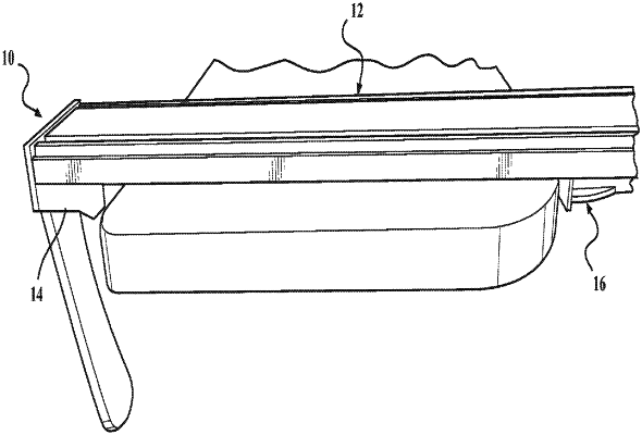
| CPC B25B 5/02 (2013.01) [B25B 1/08 (2013.01); B25B 1/2489 (2013.01); B25B 5/085 (2013.01); B25B 5/166 (2013.01); F16B 2/12 (2013.01); F16B 2/18 (2013.01)] | 7 Claims |

|
1. A straight edge clamp comprising:
an elongated body having an open channel, said open channel having a longitudinal axis, said open channel having an inner surface extending along said longitudinal axis;
a clamping head and an end stop, said clamping head is mounted within said open channel a spaced distance from said end stop, said end stop being adapted to engage an edge of a work surface, said clamping head being adapted to move within said open channel;
said end stop is fixed in place to said elongated body and doesn't move along said elongated body;
said clamping head has a locking member and a handle directly connected to said clamping head and directly controlling the movement of said locking member;
said handle and said locking member having an axis of rotation generally perpendicular to said longitudinal axis, said locking member being rotatable by said handle about said axis of rotation between a locked position and an unlocked position;
said locking member being located in said open channel and having an engagement surface protruding outwardly toward said inner surface whereby, in response to said handle rotation said locking member is rotated between said locked and said unlocked positions, in said unlocked position said locking member is retained in said open channel and said engagement surface is spaced apart from said inner surface and, in response to said locking member being in said locked position, said engagement surface is moved to engage said inner surface to lock an end stop assembly with respect to said elongated body.
|