| CPC H04N 23/685 (2023.01) [H02K 41/0354 (2013.01)] | 6 Claims |

|
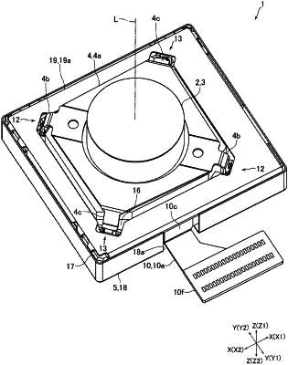
1. An optical unit with a shake correction function, comprising:
a movable body having a camera module;
an intermediate member rotatably holding the movable body;
a fixed body rotatably holding the intermediate member;
a first magnetic drive mechanism and a second magnetic drive mechanism to rotate the movable body with respect to the fixed body so that an optical axis of the camera module is inclined in an arbitrary direction; and
a first circuit board and a second circuit board at least a part of which is constituted by a flexible printed circuit board, wherein
the first magnetic drive mechanism comprises a first drive magnet and a first drive coil disposed to face each other in a first direction orthogonal to the optical axis of the camera module when the optical axis of the camera module is at a predetermined reference position;
the second magnetic drive mechanism comprises a second drive magnet and a second drive coil disposed to face each other in a second direction orthogonal to the optical axis of the camera module and the first direction when the optical axis of the camera module is at the reference position;
the fixed body comprises an intermediate member holder rotatably holding the intermediate member;
the first circuit board is pulled out from the camera module;
the first drive coil and the second drive coil are mounted on the second circuit board;
the first circuit board comprises a first band-shaped portion provided having an elongated band shape and a first connection portion to electrically connect the first circuit board and the second circuit board;
the second circuit board comprises a second band-shaped portion provided having an elongated band shape and a second connection portion to electrically connect the first circuit board and the second circuit board;
the first circuit board or the second circuit board comprises a drawer portion pulled out toward an outer peripheral side of the fixed body;
as viewed from an optical axis direction being a direction of the optical axis of the camera module when the optical axis of the camera module is at the reference position, an outer shape of the intermediate member holder has a regular-square shape or a rectangular shape, and four sides constituting an outer peripheral surface of the intermediate member holder are parallel to the first direction or the second direction; and
supposing that one of two sides of the intermediate member holder in parallel with the first direction is a first side, the other side of the two sides of the intermediate member holder in parallel with the first direction is a second side, one of two sides of the intermediate member holder in parallel with the second direction is a third side, and the other side of the two sides of the intermediate member holder in parallel with the second direction is a fourth side,
the optical axis direction when the optical axis of the camera module is at the reference position and a width direction of the first band-shaped portion are in parallel, and the first band-shaped portion is pulled around along the first side and the third side;
the optical axis direction when the optical axis of the camera module is at the reference position and a width direction of the second band-shaped portion are in parallel, and the second band-shaped portion is pulled around along the second side and the fourth side; and
the first connection portion and the second connection portion are either electrically connected while overlapping each other in the second direction on the first side or the second side or electrically connected while overlapping each other in the first direction on the third side or the fourth side.
|