| CPC H02P 25/04 (2013.01) [F21V 33/0096 (2013.01); H01H 47/02 (2013.01); H02P 1/24 (2013.01); H02P 27/16 (2013.01); H04B 3/54 (2013.01); H05B 47/16 (2020.01); H05B 47/175 (2020.01); H04B 2203/5412 (2013.01)] | 19 Claims |

|
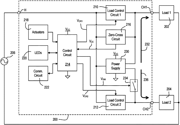
1. A load control device to control power delivered by an alternating-current (AC) power source to a first load device and a second load device, comprising:
a plurality of actuators;
a power supply circuit couplable to the AC power source;
switching circuitry selectively, reversibly, transitionable between a first state and a second state, wherein the switching circuitry:
electrically isolates the power supply circuit from the second load device when in the first state; and
electrically couples the power supply circuitry to the second load device when in the second state; and
a control circuit electrically conductively coupled to the power supply circuit and operatively coupled to the switching circuitry, the control circuit to:
receive an indication of a first actuator input;
receive an indication of a second actuator input;
generate a first control output to cause a first load control circuit to provide a continuously adjustable power level from the AC power source to the first load device responsive to the receipt of the first actuator input;
generate a second control output to cause a second load control circuit to switch between each of a plurality of power levels to stepwise adjust power delivered by the AC power source to the second load device responsive to receipt of the second actuator input;
generate a third control output to transition the switching circuitry from the first state to the second state responsive to the first load device entering a NON-CONDUCTIVE state.
|