| CPC H02M 1/0058 (2021.05) [H02M 3/33507 (2013.01)] | 19 Claims |

|
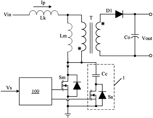
1. A control circuit for a switching converter having a main power switch and an auxiliary power switch, wherein the control circuit is configured to:
a) charge and discharge a junction capacitor of the main power switch during a turn-off period of the main power switch;
b) adjust a conduction time of the auxiliary power switch according to a difference between charged and discharged charge levels across the junction capacitor; and
c) a detection circuit configured to receive a sampling signal that represents a voltage change across the junction capacitor, and to generate a detection signal that represents the difference between the charged and discharged charge levels across the junction capacitor according to driving signal for the main power switch.
|