| CPC H02J 50/001 (2020.01) [H02J 7/345 (2013.01); H02J 50/005 (2020.01); H02M 1/0058 (2021.05); H02M 3/1588 (2013.01); H02J 2207/20 (2020.01); H02J 2207/50 (2020.01)] | 10 Claims |

|
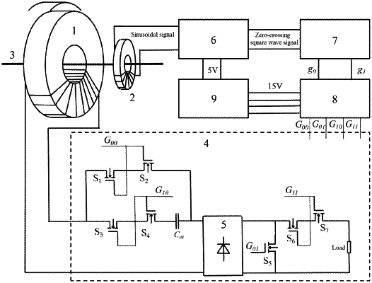
1. An electromagnetic induction type magnetic energy collector based on capacitive energy storage, comprising:
a magnetic core coil, which comprises:
a main energy acquisition coil sleeved in a main circuit to collect magnetic field energy, and
a detection coil sleeved in the main circuit to generate a sinusoidal signal for detecting zero crossing of a primary current; a main circuit module, which comprises:
a switch group S1, comprising a plurality of MOSFETs,
a switch group S2, comprising a plurality of MOSFETs, the switch group S2 and the switch group S1 being alternately turned on and off,
a first rectifier bridge connected to the switch group S2 and the switch group S1, and
a load;
a detection module, which detects the zero crossing of the primary current and comprises:
a comparator circuit connected to the detection coil to compare the sinusoidal signal and convert the sinusoidal signal into a zero-crossing square wave signal;
a control module, which is connected to the comparator circuit, determines the zero crossing of the primary current based on the zero-crossing square wave signal, and determines phases and duty ratios of a complementary control signal g0 and a complementary control signal g1 according to predetermined delay time; and
an isolation module, which is connected to the control module and comprises four optocouplers which are divided into one group for isolating and amplifying the complementary control signal g0, and the other group for isolating and amplifying the complementary control signal g1, four driving signals G00, G01, G10 and G11 generated by the four optocouplers being transmitted to gate ends and source ends of the corresponding MOSFETs to alternately turn on and off the switch group S2 and the switch group S1.
|