| CPC H01S 5/0428 (2013.01) [G01S 7/484 (2013.01); H01S 5/06216 (2013.01)] | 20 Claims |

|
1. A high-side driver method for a laser of a Lidar, comprising:
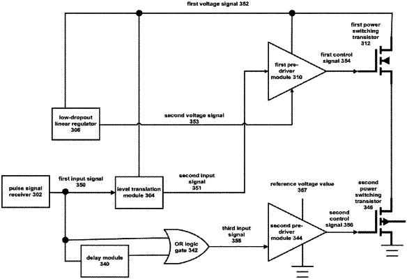
transforming a first input signal into a second input signal between a first voltage value and a second voltage value, by a level translation module, wherein the difference by the first voltage value minus the second voltage value is a reference voltage value, the second input signal is coupled to input end of a first pre-driver module;
stepping down a first voltage signal according to a first voltage difference to obtain a second voltage signal, by a low-dropout linear regulator, wherein the first voltage difference equals the reference voltage value, the second voltage signal is coupled to ground end of the first pre-driver module, the first voltage signal is used for biasing the first pre-driver module and the expected value of the first voltage signal is the first voltage value;
generating a first control signal, by the first pre-driver module, wherein the first control signal is coupled to control end of a first power switching transistor, the first voltage signal is used for biasing the first power switching transistor;
generating a pulse current for driving the laser, by the first power switching transistor,
wherein the level translation module comprises an adjustable resistor, the adjustable resistor is coupled between the first voltage signal and input end of the first pre-driver module, resistance value of the adjustable resistor is determined based on capacitance value of a first capacitor and half-wave pulse width of the first input signal, the first capacitor is parasitic capacitor from input end of the first pre-driver module to the ground, jitter of the first voltage signal is transmitted to input end of the first pre-driver module through the adjustable resistor.
|