| CPC H01M 50/186 (2021.01) [H01M 50/184 (2021.01); H01M 50/193 (2021.01); H01M 50/50 (2021.01); H01M 50/552 (2021.01)] | 15 Claims |

|
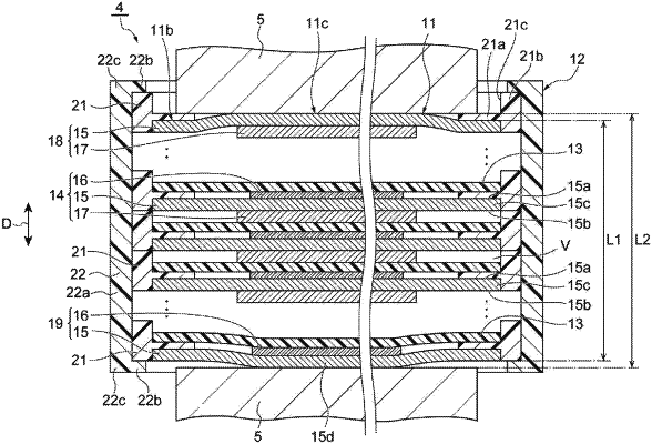
1. A power storage device, comprising:
a power storage module; and
a pair of conductive plates configured to sandwich the power storage module,
wherein the power storage module has an electrode laminate including a plurality of laminated bipolar electrodes and a pair of terminal electrodes, and a sealing body configured to seal the electrode laminate,
the pair of terminal electrodes is disposed at laminate ends of the electrode laminate and each includes an electrode plate and an active material layer provided on a surface of the electrode plate that faces an inside of the electrode laminate,
the sealing body has a pair of resin portions provided at edge portions of the pair of terminal electrodes,
at least one conductive plate of the pair of conductive plates is disposed to face a corresponding terminal electrode of the pair of terminal electrodes in a laminating direction of the electrode laminate and overlap a corresponding resin portion of the pair of resin portions when seen in the laminating direction,
the at least one conductive plate directly contacts the electrode plate of the corresponding terminal electrodes at a surface that faces away from the electrode laminate,
the active material layer of each terminal electrode is provided only on the surface of the electrode plate that faces the inside of the electrode laminate, and
the at least one conductive plate has a plurality of flow paths extending in a direction perpendicular to the laminating direction and configured to circulate coolant across a length of the at least one conductive plate in the direction perpendicular to the laminating direction.
|
|
14. A power storage device, comprising:
a plurality of power storage modules; and
a plurality of stacked conductive plates, each adjacent conductive plate being stacked with one of the plurality of power storage modules interposed therebetween,
wherein each of the power storage modules has an electrode laminate including a plurality of laminated bipolar electrodes and a pair of terminal electrodes, and a sealing body configured to seal the electrode laminate,
the pair of terminal electrodes is disposed at laminate ends of the electrode laminate and each includes an electrode plate and an active material layer provided on a surface of the electrode plate that faces an inside of the electrode laminate,
the sealing body has a pair of resin portions provided at edge portions of the pair of terminal electrodes,
at least one conductive plate of each pair of adjacent conductive plates is disposed to face a corresponding terminal electrode of the pair of terminal electrodes in a laminating direction of the electrode laminate and overlap a corresponding resin portion of the pair of resin portions when seen in the laminating direction,
the at least one conductive plate directly contacts the electrode plate of the corresponding terminal electrode at a surface of the corresponding terminal electrode that faces away from the electrode laminate,
the active material layer of each terminal electrode is provided only on the surface of the electrode plate that faces the inside of the electrode laminate, and
the at least one conductive plate has a plurality of flow paths extending in a direction perpendicular to the laminating direction and configured to circulate coolant across a length of the at least one conductive plate in the direction perpendicular to the laminating direction.
|