| CPC H01L 29/4236 (2013.01) [H01L 23/5283 (2013.01); H01L 23/53238 (2013.01); H01L 29/513 (2013.01); H01L 29/518 (2013.01); H01L 21/76846 (2013.01); H01L 21/76858 (2013.01); H01L 21/76867 (2013.01); H01L 29/401 (2013.01)] | 14 Claims |

|
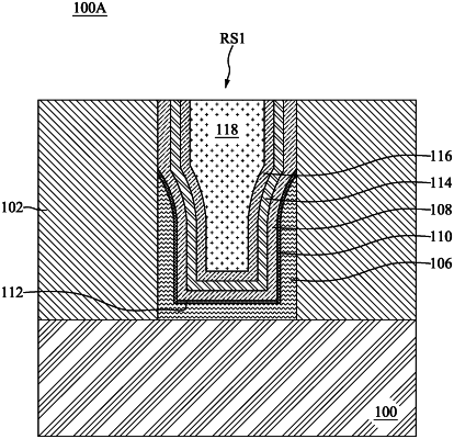
1. A recessed gate structure, comprising:
a recessed structure, wherein the recessed structure comprises a substrate, a material layer disposed on a top surface of the substrate, and a recess indented on and extended through the material layer to define a bottom surface of the recess at the top surface of the substrate, two sidewalls of the recess at two inner surfaces of the material layer respectively, and a top opening of the recess at a top surface of the material layer, such that a depth of the recess equals to a thickness of the material layer;
a conductive feature, filled in the recess of the recessed structure, wherein a top surface of the conductive feature is coplanar with the top surface of the material layer;
a first functional layer, extending between the conductive feature and the recessed structure, and comprising a first element, wherein the first functional layer, having a U-shaped configuration, having two vertical layers extending along and in direct contacting with the inner surfaces of the material layer respectively and a horizontal layer extending along and in direct contacting with the top surface of the substrate, wherein two top ends of the vertical layers of the first functional layer are formed below the top surface of the material layer;
a second functional layer, extending between the first functional layer and the conductive feature, and comprising a second element, wherein a top surface of the second functional layer is coplanar with the top surface of the material layer;
two first interfacial layers, each extending along an interface between the first functional layer and the second functional layer, and comprising the first element and the second element; and
a second interfacial layer extended from the first interfacial layers to form a U-shaped configuration,
wherein each of the first interfacial layers has a top end formed below the top surface of the material layer to cover the top end of the vertical layer of the first functional layer and in direct contacting with the inner surface of the material layer, wherein the two top ends of the first interfacial layers are covered by the second functional layer and enclosed by the first functional layer, the second functional layer and the inner surface of the material layer;
wherein a thickness of a top portion of each of the vertical layers of the first functional layer is gradually reduced toward the top end thereof to define a curved inner surface, wherein each of the first interfacial layers is extended along and is in direct contact with the curved inner surface of the top portion of each of the vertical layers until the top end of the first interfacial layer is stopped at the inner surface of the material layer.
|