| CPC G05F 1/575 (2013.01) | 17 Claims |

|
1. A system, comprising:
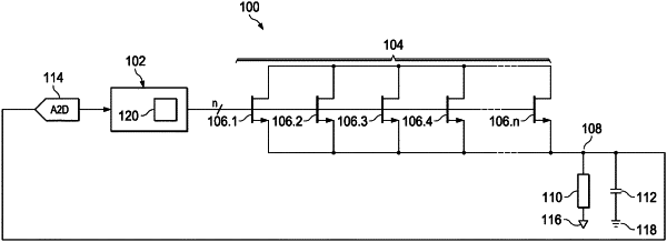
a passgate array including a first passgate transistor, a second passgate transistor, a third passgate transistor, and a fourth passgate transistor; and
a controller is configured to:
receive a feedback signal from the passgate array;
generate an error signal based on the feedback signal;
based on the error signal, determine a first number of passgate transistors to activate in a first clock cycle;
based on the first number, activate the first passgate transistor and the second passgate transistor in the first clock cycle;
received an updated feedback signal from the passgate array;
generate an updated error signal from the updated feedback signal;
based on the updated error signal, determine a second number of passgate transistors to activate in a second clock cycle;
based on the second number, deactivate the first passgate transistor and activate the third passgate transistor and the fourth passgate transistor in the second clock cycle;
received a next updated feedback signal from the passgate array;
generate a next updated error signal from the next updated feedback signal;
based on the next updated error signal, determine a third number of passgate transistors to activate in a third clock cycle; and
based on the third number, deactivate the fourth passgate transistor and activate the second passgate transistor in the third clock cycle.
|