| CPC G02B 6/4455 (2013.01) | 18 Claims |

|
1. An equipment panel comprising:
a chassis defining an interior accessible through an open front; and
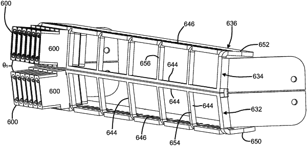
a tray disposed within the interior of the chassis, the tray being slidable relative to the chassis along a front-to-rear axis, the tray including a termination region and a splice region, the termination region being located forward of the splice region, the termination region including a lower row of front-facing ports and an upper row of front-facing ports carried with the tray when the tray is slid relative to the chassis, the splice region having a lower layer and an upper layer carried with the tray when the tray is slid relative to the chassis, each of the lower and upper layers of the splice region being configured to hold a plurality of optical splices,
wherein a fixed angle (θ1) between plug insertion axes for adapters held at the upper row and plug insertion axes for adapters held at the lower row is between about 1 degree and about 20 degrees.
|