| CPC G01N 1/34 (2013.01) [G01N 1/4077 (2013.01); G01N 33/02 (2013.01); G01N 2001/4088 (2013.01)] | 23 Claims |

|
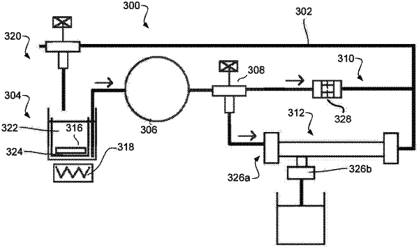
1. An apparatus for sample preparation, comprising:
a fluid circuit;
a filter loop, wherein the filter loop is incorporated into the fluid circuit;
a directional control valve configured to selectively direct fluid into the filter loop;
a cavitation chamber incorporated into the fluid circuit, the cavitation chamber including:
a channel;
a first cross-sectional area of the channel;
a second cross-sectional area of the channel, wherein the second cross-sectional area of the channel is smaller than the first cross-sectional area and oriented downstream from the first cross-sectional area with respect to fluid flow through the fluid circuit;
a third cross-sectional area of the channel, wherein the third cross-sectional area of the channel is larger than the second cross-sectional area and oriented downstream from the second cross-sectional area with respect to fluid flow through the fluid circuit, wherein the third cross-sectional area of the channel is also larger than the first cross-sectional area;
a pump in fluid communication with the cavitation chamber; and
a pressure sensor associated with the fluid circuit and positioned upstream of the cavitation chamber,
wherein the apparatus is configured to force a liquid mixture through the cavitation chamber at a pressure that separates pathogens from particles in the mixture without fragmenting at least 30% of the pathogens; and
wherein the directional control valve is configured to selectively direct fluid into the filter loop or a cavitation loop including the cavitation chamber.
|