| CPC F28F 1/128 (2013.01) [F28F 1/22 (2013.01); F28D 1/0476 (2013.01); F28F 2215/08 (2013.01); F28F 2275/04 (2013.01)] | 19 Claims |

|
1. A microchannel heat exchanger comprising:
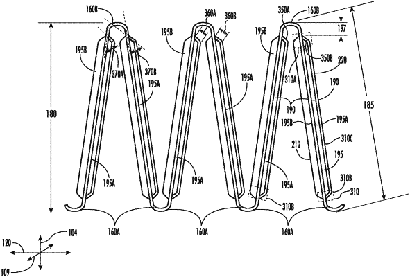
a plurality of fin segments, wherein each fin segment of the plurality of fin segments extends along a fin length direction between a fin inner end and a fin outer end and along a fin height direction between a lower fin tip and an upper fin tip,
wherein the plurality of fin segments are disposed in a triangular waveform and include: a plurality of the upper fin tips, wherein adjacent ones of the upper fin tips are longitudinally spaced apart from each other by a fin pitch; and a plurality of the lower fin tips, wherein adjacent ones of the lower fin tips are longitudinally spaced apart from each other by the fin pitch;
wherein at each fin tip, the fin segments comprise inner facing surfaces that face each other and outer facing surfaces that face away from each other;
each fin segment comprises an inner louver bank disposed between the fin inner end and a fin bisecting axis, and an outer louver bank disposed between the fin outer end and the fin bisecting axis,
each inner and outer louver bank comprising louvers,
wherein, each of the louvers comprises:
an upper transition region at an upper louver end adjacent to the upper fin tip,
a lower transition region at a lower louver end adjacent to the lower fin tip, and
a straight region extending between the upper transition region and the lower transition region,
wherein, for each of the louvers:
the transition regions along the inner facing surface at each fin tip comprise a first linear transition surface comprising a first transition length, disposed at a first transition angle to the fin segment;
the transition regions along the outer facing surface at each fin tip comprise a second linear transition surface comprising a second transition length, disposed at a second transition angle to the fin segment; and
wherein, for each of the louvers:
the first transition length is longer than the second transition length; and
the first transition angle is smaller than the second transition angle;
wherein each of the louvers includes a louver slat and louver slot adjacent to each other in a depth direction, the louver slot formed by a slit that extends through a fin thickness of the fin, the louver slat and slot being formed by cutting the slit into the fin segment and pressing a form of the louver slat, thereby press-forming a shape of the louver slot into the fin segment,
the upper and lower louver ends of the inner louver bank define an inner-side louver angle that is acute relative to the fin length direction, such that each louver slot forms outwardly splayed aperture, expanding toward adjacent ones of the upper and lower fin tips, defining an air scoop, and wherein the outer louver bank mirrors the inner louver bank about the fin bisecting axis.
|