| CPC F23Q 13/00 (2013.01) [F02K 3/02 (2013.01); F23R 3/18 (2013.01); F23R 3/28 (2013.01); H05H 1/24 (2013.01); H05H 2245/80 (2021.05)] | 8 Claims |

|
1. A combustion system comprising:
a combustion chamber extending in an axial direction between an inlet and an outlet, the combustion chamber configured to receive an airflow through the inlet and to discharge the airflow through the outlet;
a fuel injection port configured to inject fuel into the airflow to form an air-fuel mixture;
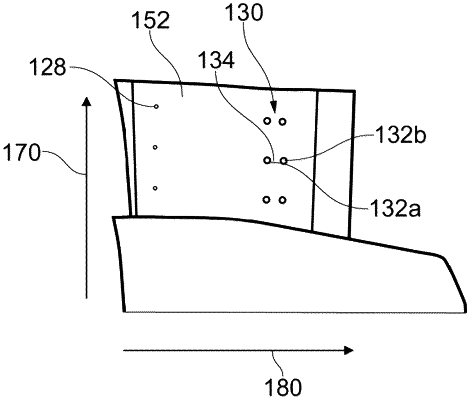
an ignition system for igniting the air-fuel mixture in the combustion chamber, the ignition system comprising an array of electrical plasma initiation points disposed downstream of the fuel injection port, and distributed radially and circumferentially around the combustion chamber;
a vane structure in the combustion chamber, the vane structure configured to guide the airflow from the inlet, wherein the array of electrical plasma initiation points are disposed on the vane structure and distributed radially and circumferentially around the vane structure,
wherein each electrical plasma initiation point comprises a pair of electrodes configured to apply a voltage across an electrode gap between the pair of electrodes to produce plasma within the air-fuel mixture passing between the electrodes, thereby igniting the air-fuel mixture; and
wherein the vane structure comprises a circumferentially distributed plurality of vanes, wherein each electrical plasma initiation point comprises a first electrode on a first vane and a second electrode on a circumferentially adjacent second vane.
|