| CPC F02G 1/0435 (2013.01) [F01B 7/12 (2013.01); F02G 1/043 (2013.01); F02G 1/044 (2013.01); F02G 1/0535 (2013.01); F16C 9/04 (2013.01); F16C 11/04 (2013.01); F16C 11/12 (2013.01); F16J 3/06 (2013.01); F16J 15/52 (2013.01); F02G 2244/08 (2013.01); F02G 2253/03 (2013.01); F02G 2253/08 (2013.01); F02G 2253/80 (2013.01); F02G 2270/45 (2013.01); F02G 2270/50 (2013.01); F02G 2270/85 (2013.01)] | 19 Claims |

|
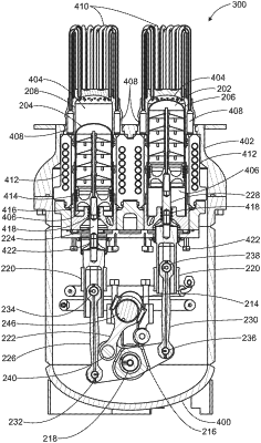
1. A rocking beam drive mechanism for a machine comprising:
a rigid structure having;
a crankcase, the crankcase housing a rocking beam and housing a first portion of at least one coupling assembly;
the crankcase having a lubricating pump;
a cylinder housing for housing at least one cylinder, and a second portion of the at least one coupling assembly;
a crankshaft, fixed in relation to the rigid structure;
the rocking beam having a rocker pivot, the rocker pivot is fixed in place by a rocking beam shaft and is positioned at a midpoint within the rocking beam;
the rocking beam shaft is fixed in place in relation to the crankshaft;
at least one piston, the piston at least partially housed within the cylinder housing whereby the piston is capable of substantially linearly reciprocating within the respective cylinder;
the at least one coupling assembly having a proximal end and a distal end, the proximal end being connected to the piston and the distal end being connected to the rocking beam by an end pivot, whereby linear motion of the piston is converted to rotary motion of the rocking beam; and
a seal sealably connected to a piston rod wherein the seal is a rolling diaphragm, the rolling diaphragm comprising a non-woven fabric;
an airlock located between the crankcase and the cylinder housing, the airlock disposed above the rolling diaphragm and the crankcase disposed below the rolling diaphragm; and
a pressure regulator maintaining a constant pressure differential between the airlock and the crankcase.
|