|
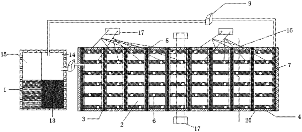
1. A device for mud solidification based on electro-osmosis well points cooperating with well-points dewatering, comprising a mud tank (1), a sedimentation tank (2), well point pipe support beams (3), well point pipe positioning frame beams (4), channel steel bearing beams (5), well point pipes (6), a water collecting main pipe (7), connecting elbows (8), a vacuum water pump house (9), a mud discharging pipe (10), a slurry storage tank (13), a primary cleaning tank (14), a secondary cleaning tank (15), a connecting wire (16), a DC generator (17) and filter pipes (18); wherein the sedimentation tank (2) has a rectangular structure, the channel steel bearing beams (5) are laid on a tank wall inner side of the sedimentation tank (2), the well point pipe support beams (3) are laid at a top of the sedimentation tank (2) at equal intervals in a direction parallel to a short edge of the sedimentation tank, and the well point pipe positioning frame beams (4) are arranged on the well point pipe support beams (3) at equal intervals in a direction parallel to a long edge of the sedimentation tank; well point pipe holes are preset in the well point pipe positioning frame beams (4), the well point pipes (6) are arranged in the well point pipe holes, and a lower portion of each well point pipe (6) is one filter pipe (18); the water collecting main pipe (7) is arranged at a top of the well point pipe (6) in the direction parallel to the short edge of the sedimentation tank, the top of the well point pipe (6) is connected to the water collecting main pipe (7) through a corresponding one of the connecting elbows (8); the well point pipe (6) is connected to the DC generator (17) through the connecting wire (16); the water collecting main pipe (7) is communicated with the primary cleaning tank (14) through the vacuum water pump house (9), the primary cleaning tank (14) is communicated with the secondary cleaning tank (15) and the slurry storage tank (13), and the sedimentation tank (2) is communicated with the mud tank (1) through the mud discharging pipe (10).
|
