| CPC B60C 9/20 (2013.01) [B60C 3/04 (2013.01); B60C 2009/2012 (2013.01); B60C 2009/2035 (2013.01)] | 18 Claims |

|
1. A pneumatic tire, comprising:
a tread portion extending in a tire circumferential direction and having an annular shape;
a pair of sidewall portions respectively disposed on both sides of the tread portion;
a pair of bead portions each disposed on an inner side of the pair of sidewall portions in a tire radial direction;
at least one carcass layer mounted between the pair of bead portions and folded back from a tire inner side toward an outer side around a bead core each provided in the bead portions;
a plurality of belt layers disposed on an outer circumferential side of the carcass layer in the tread portion; and
a plurality of circumferential grooves extending along the tire circumferential direction on an outer surface of the tread portion;
the plurality of belt layers comprising a cross belt pair made of two belt layers configured to reverse inclination directions of reinforcing cords constituting each of the belt layers to cause the reinforcing cords to intersect with each other,
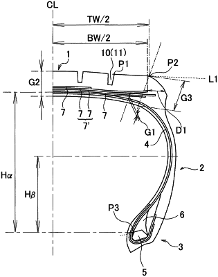
a distance D1 between a tire outer surface and an end point of the cross belt pair on the outer side in the tire radial direction and the outer side in a tire width direction measured in parallel to a line segment L1 connecting a ground contact edge P2 and an edge portion P1 of an outermost groove on the outer side in the tire width direction located on an outermost side in the tire width direction of the plurality of circumferential grooves satisfying a relationship of 15 mm≤DI≤25 mm,
a distance G1 between the plurality of belt layers and the carcass layer measured on a normal line of the carcass layer passing through an outer end point in an effective width of the cross belt pair satisfying a relationship of 2.5 mm≤ G1≤9.0 mm, and
a radial height Ha from a position of a core separation point P3 defined as an intersection point of the carcass layer with an extension line of a side on the outer side of the bead core in the tire radial direction to a maximum outer diameter position of the carcass layer and a radial height HB from the position of the core separation point P3 to a tire maximum width position satisfying a relationship of 0.55≤HB/Hα≤0.65.
|