| CPC B60C 11/1315 (2013.01) [B60C 11/0309 (2013.01); B60C 11/1323 (2013.01); B60C 11/1353 (2013.01); B60C 2011/0346 (2013.01); B60C 2011/0362 (2013.01); B60C 2011/0381 (2013.01); B60C 2011/039 (2013.01)] | 15 Claims |

|
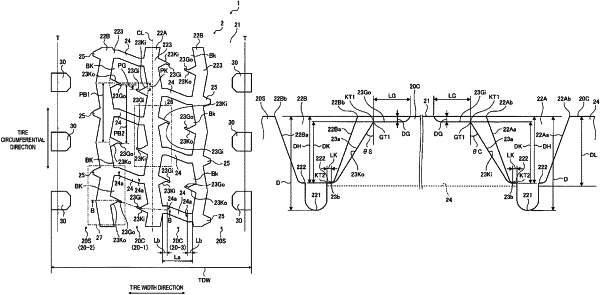
1. A pneumatic tire, comprising:
a circumferential main groove extending in a tire circumferential direction in a tread surface of a tread portion;
the circumferential main groove being segmented into an outer side in tire radial direction and an inner side in tire radial direction by drawing an imaginary segment line parallel with a straight line connecting each of groove opening edges at a position of ½ of a groove depth in a meridian cross-section,
a cross-sectional area SU on the outer side in tire radial direction and a cross-sectional area SD on the inner side in tire radial direction satisfying the relationship 0.15≤SD/SU≤0.60,
the circumferential main groove having a zigzag shape that bends in a tire width direction, and
the circumferential main groove having a pitch length P1 of one period of the zigzag shape and a tire circumferential length TL in the tire circumferential direction satisfying a relationship 0.005≤P1/TL≤0.019;
a plurality of circumferential main grooves provided side by side in the tire width direction;
a plurality of lug grooves provided side by side in the tire circumferential direction to connect mutual bent portions of the zigzag shape closest in the tire width direction with respect to two of the plurality of circumferential main grooves adjacent to each other in the tire width direction; and
a block defined by the two of the plurality of circumferential main grooves adjacent to each other in the tire width direction and two of the plurality of lug grooves adjacent to each other in the tire circumferential direction, wherein
one of the plurality of circumferential main grooves defining the block is disposed closer to a tire equatorial plane, and the other of the plurality of circumferential main grooves is disposed closer to a tire ground contact edge,
the block includes notch portions respectively connected to each of the plurality of circumferential main grooves on both sides in the tire width direction and terminating inside the block,
each of the notch portions comprising an inclined portion that is inclined with respect to a normal line of the tread surface toward a groove bottom of each of the circumferential main grooves, and
each of the inclined portions having inclination angles, where a notch connected to the one of the plurality of circumferential main grooves has an inclination angle θC toward a groove bottom of the one of the plurality of circumferential main grooves and a notch connected to the other of the plurality of circumferential main grooves has an inclination angle θS toward a groove bottom of the other of the plurality of circumferential main grooves that satisfy the relationships θC≤20° and θC<θS.
|