| CPC B41J 2/175 (2013.01) [B41J 2/17503 (2013.01); B41J 2/17506 (2013.01); B41J 2/17513 (2013.01); B41J 2/1752 (2013.01); B41J 2/17553 (2013.01); B41J 29/02 (2013.01); B41J 29/023 (2013.01); G06K 15/105 (2013.01); B41J 2/005 (2013.01); B41J 2/01 (2013.01); B41J 2/17 (2013.01)] | 18 Claims |
|
1. A liquid jetting apparatus, comprising:
a casing;
a tank positioned inside the casing and configured to store liquid, the tank having a left wall, a right wall, a rear wall, and an inlet through the tank;
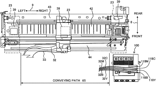
a conveying mechanism positioned inside the casing, the conveying mechanism being configured to convey a recording medium along a conveying path extending in a front-rear direction;
a carriage positioned inside the casing above the conveying path, the carriage being configured to move in a left-right direction in which the left wall and the right wall face each other so as to define a movement area having a range in the left-right direction; and
a head mounted on the carriage and having a nozzle, the nozzle being configured to jet the liquid flowed out from the tank onto the recording medium conveyed by the conveying mechanism,
wherein the tank is positioned outside the conveying path in the left-right direction,
wherein in a state of the carriage being positioned at a right end of the movement area, a first part of the tank is positioned left with respect to a right end of the head, and
wherein in the state of the carriage being positioned at the right end of the movement area, a second part of the tank is positioned right with respect to the right end of the head.
|