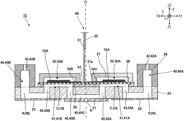
| CPC B41J 2/14201 (2013.01) | 16 Claims |

|
1. A liquid ejecting head comprising:
a line of first pressure chambers including a plurality of first pressure chambers arranged in a first direction;
a line of second pressure chambers including a plurality of second pressure chambers arranged in the first direction, the line of second pressure chambers being provided at a different position from the first pressure chambers in a second direction intersecting with the first direction;
a line of nozzles including a plurality of nozzles arranged in the first direction and communicating with the first pressure chambers and the second pressure chambers in common, respectively;
first piezoelectric bodies provided corresponding to the plurality of first pressure chambers;
first individual electrodes individually provided to the plurality of first pressure chambers and being electrically coupled to the first piezoelectric bodies;
a first common electrode provided in common to the plurality of first pressure chambers and electrically coupled to the first piezoelectric bodies;
second piezoelectric bodies provided corresponding to the plurality of second pressure chambers;
second individual electrodes individually provided to the plurality of second pressure chambers and being electrically coupled to the second piezoelectric bodies;
a second common electrode provided in common to the plurality of second pressure chambers and electrically coupled to the second piezoelectric bodies;
a wiring member that supplies a voltage to the first individual electrodes, the first common electrode, the second individual electrodes, and the second common electrode;
a first individual line that electrically couples the first individual electrode to the wiring member;
a first common line that electrically couples the first common electrode to the wiring member;
a second individual line that electrically couples the second individual electrode to the wiring member; and
a second common line that electrically couples the second common electrode to the wiring member, wherein
the wiring member is electrically coupled to the first common line at a position shifted to one side in the first direction relative to a center in the first direction of the lines of first and second pressure chambers, and
the wiring member is electrically coupled to the second common line at a position shifted to another side in the first direction relative to the center in the first direction of the lines of first and second pressure chambers.
|