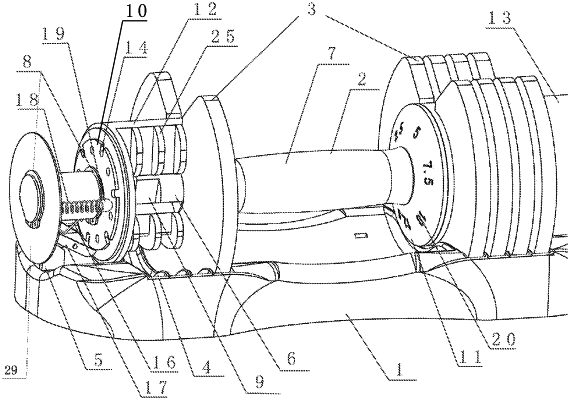
| CPC A63B 21/075 (2013.01) [A63B 21/0726 (2013.01); A63B 21/0728 (2013.01)] | 4 Claims |

|
1. An adjustable dumbbell, comprising:
a base (1) and a dumbbell body; wherein:
the dumbbell body comprises a handle (2);
the handle (2) comprises a combination of a central shaft (6) and a handle sleeve (7), wherein the central shaft (6) is also connected with a dividing disc (10), a shift piece (11) and a bell box (12);
the bell box (12) is an elliptic cylinder, and is equipped with a bell box isolation wall (25) for fixing bell pieces with equal distance between the bell pieces and one side of the bell box (12) is provided with a semicircular hole (26), and the semicircular hole (26) of the bell box (12) and a control hole (24) of each of the bell pieces are connected via a gear step (9);
each of the bell pieces is a large semicircle with a flat bottom, and the control hole (24) of each of the bell pieces is located at an intersection of a positioning opening (23) and a bell piece center of each of the bell pieces;
the dividing disc (10) is provided with locking piece positioning grooves (14) and ball shift holes (15), wherein the dividing disc (10) is a circular plate, in which a radius of one part of the dividing disc (10) is larger than that of other parts of the dividing disc (10); the dividing disc is connected with the central shaft (6) through a snap spring groove (8) and a large semicircle dividing disc limiting hole (27) in a center of the dividing disc (10); the locking piece positioning grooves (14) are grooves distributed on a periphery of the dividing disc (10), and the ball shift holes (15) are round holes distributed on an inner side of the dividing disc;
the shift piece (11) is a circle, and a positioning structure for the central shaft (6) is a semicircle type dividing disc limiting hole (27) in a center of the shift piece (11);
a surface of the shift piece (11) contains a gear mark (20) corresponding to the locking piece positioning grooves (14) of the dividing disc (10);
the bell box (12) is connected with a bell box cover (13); the bell box cover (13) is connected with a locking piece spring (16) and a ball spring (18); the locking piece spring (16) is connected with a locking piece (17); the locking piece (17) is connected with the ball spring (18); and a steel ball (19) is connected with the ball spring (18);
the bell box cover (13) is a cylinder, which contains a plurality of holes for fixing and placing the locking piece spring (16), the locking piece (17), and the ball spring (18); the bell box cover (13) is also provided with a baffle (29), which is connected with the central shaft (6) through the snap spring groove (8);
when the dumbbell body is placed on the base (1), an unlocking device (5) applies a force to the locking piece spring (16) to push the locking piece (17) to separate the locking piece (17) from one of the locking piece positioning grooves (14) causing the unlocking device (5) to be in an unlocking state, wherein the handle (2) is configured to rotate to select a gear; wherein the unlocking device (5) is located at the same position on each of both sides of the base (1), the unlocking device (5) is a right angle trapezoid perpendicular to a surface of the base (1) and positioned adjacent to an outer edge of the base (1);
when the handle (2) rotates, the ball spring (18) causes the steel ball (19) to rotate on the dividing disc (10) and fall into one of the ball shift holes (15);
the shift piece (11) synchronously rotates to a required gear mark (20); and
when the dumbbell body leaves the base (1), thrust on the locking piece (17) is removed and the locking piece (17) is inserted into one of the locking piece positioning grooves (14) of the dividing disc (10) to lock a rotation of the handle (2).
|