| CPC A61B 34/30 (2016.02) [A61B 17/00234 (2013.01); A61B 34/10 (2016.02); A61B 34/20 (2016.02); A61B 34/25 (2016.02); A61B 34/71 (2016.02); A61B 90/98 (2016.02); A61B 1/00149 (2013.01); A61B 2017/00323 (2013.01); A61B 2017/00327 (2013.01); A61B 2017/00477 (2013.01); A61B 2034/2051 (2016.02); A61B 2034/2061 (2016.02); A61B 2034/301 (2016.02); A61B 2034/715 (2016.02); A61B 2090/064 (2016.02); A61B 2090/067 (2016.02); A61B 2217/005 (2013.01); A61B 2217/007 (2013.01)] | 20 Claims |

|
1. A robotic system, comprising:
a robotic arm comprising:
a series of linkages connected by a series of joints; and
two or more instrument drivers arranged linearly to form a virtual rail, the two or more instrument drivers including a first instrument driver coupled to a distal end of the series of linkages; and
a medical instrument, comprising:
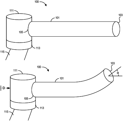
an elongated shaft extending between a distal portion and a proximal portion and coupled to the two or more instrument drivers, the elongated shaft configured for insertion, in use, into a lumen of a patient;
an instrument base connected to the proximal portion of the elongated shaft, the instrument base including an attachment interface configured to facilitate attachment to the robotic arm;
a non-transitory computer readable medium storing a compression compensation parameter that relates movement of the elongated shaft to axial compression of the elongated shaft; and
a pull wire connected to the distal portion of the elongated shaft, the pull wire extending along the elongated shaft between the distal portion and a drive input positioned at the instrument base, the drive input configured to actuate the pull wire to cause movement of the elongated shaft;
wherein the robotic arm is configured to move the two or more instrument drivers along the virtual rail to advance or retract the instrument base based at least in part on the stored compression compensation parameter.
|