| CPC A61B 17/068 (2013.01) [A61B 17/00 (2013.01); A61B 17/07207 (2013.01); H02P 7/29 (2013.01); A61B 2017/00017 (2013.01); A61B 2017/00137 (2013.01); A61B 2017/00398 (2013.01); A61B 2017/0046 (2013.01); A61B 2017/00486 (2013.01); A61B 2017/00734 (2013.01)] | 6 Claims |

|
1. A surgical stapler, comprising:
an end effector comprising a first jaw and a second jaw movable relative to the first jaw to clamp tissue therebetween;
a drive system comprising a driver to actuate at least one function of the surgical stapler;
an electric motor mechanically coupled to the drive system;
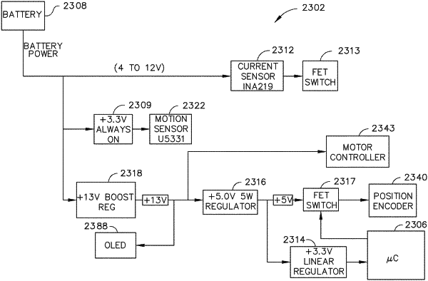
a sensor;
a battery electrically couplable to the electric motor; and
a control circuit electrically connected to the electric motor, wherein the control circuit comprises a pulse width modulation circuit and is configured to control a force applied to the drive system based on:
a plurality of battery current measurements; and
a plurality of predicted recirculating current values, wherein the control circuit is configured to:
actuate the driver with the electric motor through a closure stroke;
monitor a signal of the sensor during the closure stroke;
interrupt the actuation of the driver during the closure stroke based on the monitored signal of the sensor;
actuate the driver through a staple firing stroke with the electric motor;
monitor a current drawn by the electric motor during the staple firing stroke; and
interrupt the actuation of the driver during the staple firing stroke based on the monitored current being outside of a predetermined range of current.
|