| CPC A45D 40/0068 (2013.01) [A45D 34/00 (2013.01); B65D 51/18 (2013.01); B65D 77/0493 (2013.01); A45D 2034/005 (2013.01); B65D 2251/0015 (2013.01); B65D 2251/0093 (2013.01)] | 16 Claims |

|
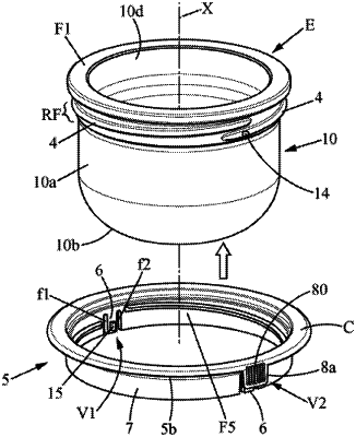
1. A container for containing a product, formed by mounting, along a longitudinal axis, an internal receptacle within an external receptacle, using a coupling insert of annular shape, the container comprising:
the internal receptacle, made of glass, defining a volume for receiving the product and extending between a bottom and an upper face provided with an opening bordered by an annular upper end of the internal receptacle;
the external receptacle, made of glass, suitable for housing the internal receptacle internally within an inside volume accessible through a longitudinal opening defined by a neck or lid receiving member of the external receptacle; and
the coupling insert, which is annular and integral with the internal receptacle, the coupling insert being suitable for directly supporting the annular upper end so as to create space between the internal receptacle and the external receptacle while maintaining the internal receptacle in a predetermined axial position relative to the external receptacle;
an annular peripheral attachment region being provided on the internal receptacle, at the annular upper end or in a downwardly offset position adjacent to the annular upper end, so as to engage an inner engagement face of the coupling insert with the annular peripheral attachment region and thus obtain a coupling state to immobilize the coupling insert on the internal receptacle,
the external receptacle being suitable for internally receiving an insertion portion of the coupling insert which includes said inner engagement face,
wherein the coupling state of the coupling insert around the internal receptacle results from a relative rotation between the coupling insert and the internal receptacle, to reach a locking configuration in which a lower portion of the coupling insert, constituting the insertion portion, is rotationally locked at or under the annular upper end, and
wherein the insertion portion of the coupling insert has at least one elastically deformable portion which is:
suitable for engaging with the annular peripheral attachment region and locking the coupling state, and
delimited by slots or indentations within the thickness of the insertion portion,
wherein the insertion portion is annular, the coupling insert comprising:
first rotation locking members capable of being attached on the annular peripheral attachment region, opposing the rotation of the coupling insert around the internal receptacle in order to lock the coupling state, and each formed in the inner engagement face, in the at least one elastically deformable portion, each elastically deformable portion being separated from the rest of the insertion portion by slots, and
second rotation locking members opposing the rotation of the external receptacle around the coupling insert, the second rotation locking members being configured to maintain an axial attachment position of the coupling insert, in which the insertion portion is inserted such that the internal receptacle is in said predetermined axial position which is fixed when the coupling state and the locking configuration are obtained.
|