| CPC A01D 43/0638 (2013.01) [A01D 45/00 (2013.01)] | 9 Claims |

|
1. A mowing method for compensatory growth of a desert plant Anabasis aphylla, comprising:
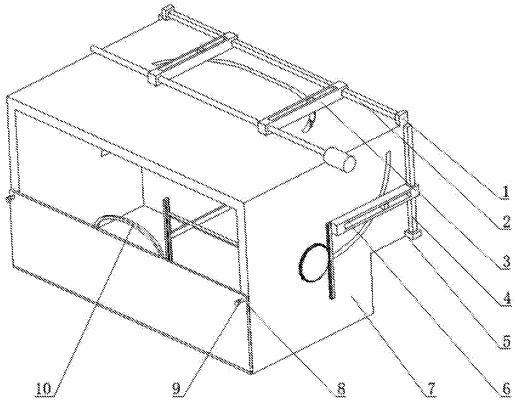
a frame body (7), symmetrically arranged circular grooves (12) and straight grooves (41) being disposed on the frame body (7), the symmetrically arranged circular grooves (12) being communicated with the straight grooves (41), and symmetrically arranged circular arc grooves (14) being disposed on the frame body (7),
the frame body (7) being fixedly connected to a motor (13), an output shaft of the motor (13) being fixedly connected to a threaded rod (11), and two reverse threads of the threaded rod (11) being threadedly connected to corresponding transverse grooves (3),
sliding blocks II (18) being embedded in the symmetrically arranged transverse grooves (3), the symmetrically arranged sliding blocks II (18) being fixedly connected to round rods II (19), and the symmetrically arranged round rods II (19) matching the corresponding circular grooves (12) and the straight grooves (41), and being fixedly connected to vertical grooves I (20),
one of the vertical grooves I (20) being fixedly connected to a push plate I (21), and the symmetrically arranged push plate I (21) being fixedly connected to symmetrically arranged baffle plates II (22),
another of the vertical grooves I (20) being fixedly connected to a push plate II (23), symmetrically arranged grooves (24) being disposed on the push plate II (23), and the symmetrically arranged baffle plates II (22) matching the symmetrically arranged grooves (24),
a sliding block III (32) being embedded in the other vertical groove I (20), the sliding block III (32) being fixedly connected to a bending rod (33), the bending rod (33) being fixedly connected to a vertical plate (38), the vertical plate (38) being connected to a center shaft of a gear II (37) via a bearing, and the center shaft of the gear II (37) being fixedly connected to a transverse plate (35),
the push plate II (23) being fixedly connected to an L-shaped rod (34), the L-shaped rod (34) being fixedly connected to a gear rack II (36), and the gear II (37) matching the gear rack II (36), and
the frame body (7) being fixedly connected to a guide plate (15), a round rod III (28) being arranged in a vertical groove II (31), the vertical groove II (31) being fixedly connected to a square rod (30), and the square rod (30) passing through the guide plate (15) and being fixedly connected to a cutting knife (29); and
comprising the following steps of:
step 1: mounting the frame body (7) on movable equipment;
step 2: driving the movable equipment to a working area;
step 3: intermittently operating the movable equipment to allow an area formed by the push plate I (21), the baffle plates II (22) and the push plate II (23) to be exactly opposite to a suitable number of Anabasis aphylla;
step 4: starting the motor (13), allowing the push plate I (21), the baffle plates II (22) and the push plate II (23) to encircle Anabasis aphylla driven by relevant elements, pushing, by the push plate I (21) and the push plate II (23), Anabasis aphylla to move towards a middle, and pushing, by the transverse plate (35), Anabasis aphylla to form into a > shape, with an opening of the > shape towards the push plate II (23);
step 5: contacting, by the cutting knife (29), Anabasis aphylla and cutting the same along a position slightly above the transverses plate (35); and
step 6: starting the motor (13) in reverse to move the transverse plate (35) in reverse, Anabasis aphylla falling onto the transverse plate (35) until the transverse plate (35) swings to allow Anabasis aphylla to fall onto a bottom plate of the frame body (7), and starting the motor (13) to restore the transverse plate (35) to be horizontal.
|