| CPC H04L 67/1095 (2013.01) [G06F 16/27 (2019.01); G06Q 10/101 (2013.01)] | 12 Claims |

|
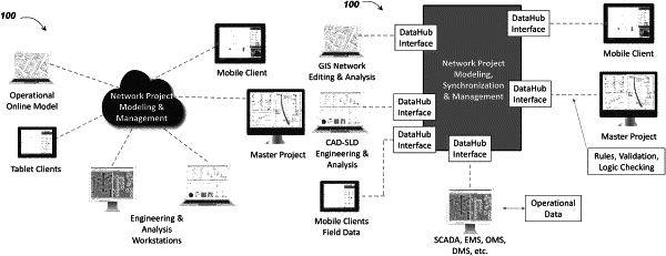
1. A system for utility network system engineering, comprising:
a server connected to a plurality of client devices via a network, the server configured to:
generate a utility network system model having project information data;
upon receiving a first request from a client device of the plurality of client devices, transmit the utility network system model to the client device;
receive first change data from the client device, wherein the first change data comprises change data for at least one of utility network asset data, engineering change data, and network configuration change data;
synchronize the first change data with the project information data on a queue- based basis; and
transmit the synchronized project information to one or more client devices associated with a list of registered project list users,
wherein each client device of the plurality of client devices comprises a thin client configured to:
generate a graphical user interface for display on a display of the each client device of the plurality of client devices, wherein the graphical user interface is at least one of web-based schematic, single-line diagram view, geospatial view, fluid flow, cross-sectional view, 3D view, layout view, street view, process diagram, protection view, and trending chart;
generate the first request;
transmit the first request to the server; receive the utility network system model;
store the utility network system model in a client device local database;
upon receiving one or more local change data, generate the first change data;
transmit the first change data to the server; and
upon receiving the synchronized project information, update the graphical user interface with one or more data from the synchronized project information,
wherein the graphical user interface further comprises a network view which displays connectivity details from a power, water or gas distribution station.
|