| CPC H02M 3/1563 (2013.01) [H02M 1/0032 (2021.05); H02M 3/156 (2013.01); H02M 3/157 (2013.01); H02M 1/14 (2013.01); H02M 3/1582 (2013.01)] | 12 Claims |

|
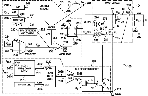
1. A DC-DC regulator system, comprising:
a power circuit having a first input, a second input and an output;
a control circuit having a first input coupled to the output of the power circuit, a second input, a first output and a second output; and
an out-of-audio circuit having a first input, a second input coupled to the second output of the control circuit, a third input coupled to the output of the power circuit, and a fourth input;
wherein the out-of-audio circuit comprises:
a frequency comparison circuit having a first input coupled to the second output of the control circuit and a second input coupled to the first input of the out-of-audio circuit; and
a counter having a first input coupled to an output of the frequency comparison circuit and having a second input coupled to receive a bandwidth control clock signal;
wherein the frequency comparison circuit is configured to provide a logic high voltage at the output of the frequency comparison circuit when a frequency of a converter clock signal is lower than a minimum threshold frequency and to provide a logic low voltage at the output of the frequency comparison circuit when the frequency of the converter clock signal is higher than the minimum threshold frequency;
wherein the counter is configured to provide a count value at an output of the counter responsive to the bandwidth control clock signal, and wherein the counter is configured to increment the count value responsive to the logic high voltage and to decrement the count value responsive to the logic low voltage.
|