| CPC H02K 9/227 (2021.01) [H02K 5/136 (2013.01); H02K 11/33 (2016.01); H02K 2211/03 (2013.01)] | 13 Claims |

|
1. A rotary electric machine comprising a control unit, wherein
the control unit includes a switching element, a capacitor, a choke coil, and a heat sink,
the switching element is joined to the heat sink via a switching element heat dissipation material,
the heat sink includes
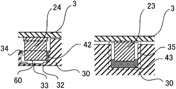
a recess-shaped choke coil housing portion having a bottom surface joined to an upper surface of the choke coil via a choke coil heat dissipation material, and
a recess-shaped capacitor housing portion having an inner peripheral side surface joined to an outer peripheral side surface of the capacitor via a capacitor heat dissipation material, and
the capacitor housing portion includes
an explosion-proof valve recess located at a position facing an explosion-proof valve of the capacitor, and
a communication passage providing communication between a drive circuit board and the explosion-proof valve.
|