| CPC H02K 29/03 (2013.01) [H02K 1/16 (2013.01); H02K 1/2713 (2013.01); H02K 3/12 (2013.01); H02K 3/34 (2013.01); H02K 21/24 (2013.01)] | 5 Claims |

|
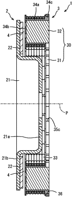
1. An axial gap motor comprising:
a rotor rotatable about a rotation axis, the rotor including a plurality of field magnets arranged around the rotation axis;
a cylindrical stator core aligned with the rotor in an axial direction of the stator core, such that the rotation axis of the rotor is in the axial direction, the stator core including
a yoke, and
a plurality of teeth arranged along a circumferential direction of the stator core around the yoke; and
a plurality of stator coils respectively wound around the plurality of teeth, wherein
each of the plurality of teeth is formed of pressed particles;
in a view of the plurality of teeth in the axial direction of the stator core, each of the plurality of teeth extends along a radial direction of the stator core, and has
a tooth-radial-direction-outer-end portion located at an outer end of said each tooth in the radial direction of the stator core,
a tooth-radial-direction-inner-end portion located at an inner end of said each tooth in the radial direction of the stator core, and
a tooth-radial-direction-inner portion located inward of a center of said each tooth in the radial direction of the stator core,
said each tooth being formed of a trapezoidal shape in which a circumferential length of the tooth-radial-direction-outer-end portion is larger than a circumferential length of the tooth-radial-direction-inner-end portion;
each two of the plurality of teeth adjacent to each other in the circumferential direction of the stator core form a slot for accommodating the stator coil, the slot being of a rectangular shape in said view of the plurality of teeth in the axial direction;
each of the plurality of field magnets has
a magnet-radial-direction-inner-end portion located at an inner end of said each field magnet in the radial direction of the stator core, and
a magnet-radial-direction-outer-end portion located at an outer end of said each field magnet in the radial direction of the stator core,
a circumferential length of the magnet-radial-direction-inner-end portion being greater than or equal to a circumferential length of the magnet-radial-direction-outer-end portion; and
the rotor and the stator core are configured to rotate relative to each other about the rotation axis, by which, in a view of the rotor and the stator core in the axial direction of the stator core,
a part of each of the plurality of field magnet first overlaps with the tooth-radial-direction-inner portion of one of the plurality of teeth, and
in a case where the plurality of field magnets are located at a quadrature axis (q-axis) position with respect to the plurality of teeth, each adjacent two of the plurality of field magnets overlap with one of the plurality of teeth.
|