| CPC G11B 5/6029 (2013.01) [G11B 5/607 (2013.01); H03F 1/0261 (2013.01)] | 20 Claims |

|
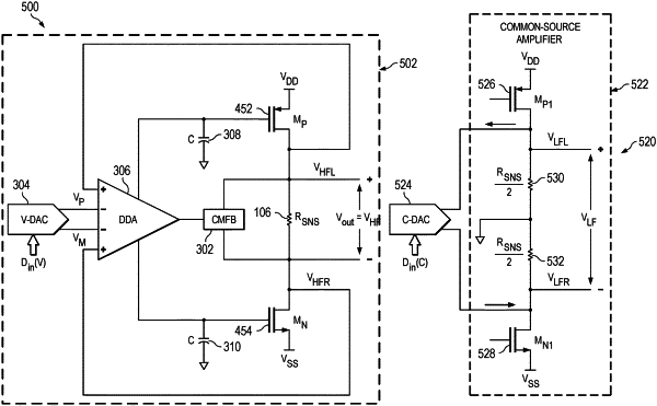
15. A low-frequency recovery circuit, comprising:
a current digital to analog converter (C-DAC);
a pair of transistors arranged as a high-impedance structure and coupled to the C-DAC;
a pair of resistors having a resistance value equal to half a resistance of a resistive sensor, the pair of resistors arranged between the pair of transistors and coupled to the C-DAC, the resistive sensor used to measure a fly height of a hard disk drive; and
a gain circuit coupled to shared nodes between the pair of transistors and the pair of resistors, the low-frequency recovery circuit configured to extract and amplify a low-frequency component of a sensing signal of the resistive sensor, the sensing signal indicating the fly height.
|