| CPC G06F 1/12 (2013.01) | 18 Claims |

|
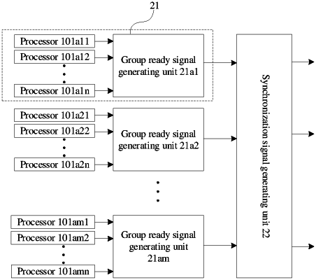
1. A synchronization signal generating circuit for generating a synchronization signal for M node groups, each of the node groups comprising at least one node, and M being an integer greater than or equal to 1, wherein
a first node group in the M node groups comprises K nodes, and K is an integer greater than or equal to 1, and the node is a core a processor;
the synchronization signal generating circuit comprises: a synchronization signal generating sub-circuit and M group ready signal generating sub-circuits;
the M group ready signal generating sub-circuits are in one-to-one correspondence with the M node groups;
a first group ready signal generating sub-circuit of the M group ready signal generating sub-circuits is connected to K nodes in the first node group to be synchronized, wherein the first group ready signal generating sub-circuit is configured to generate a first to-be-started signal for the first node group to be synchronized;
output terminals of the M group ready signal generating sub-circuits are connected to the synchronization signal generating sub-circuit; and
the synchronization signal generating sub-circuit generates a first synchronization signal based on the first to-be-started signal, wherein the first synchronization signal is configured to instruct the K nodes in the first node group to start synchronization;
the synchronization signal generating sub-circuit comprises: M shields, M to-be-synchronized group indicators, and M group synchronization signal generating sub-circuits;
the M to-be-synchronized group indicators are respectively connected to the M shields;
an input terminal of each of the M shields is connected to the output terminals of the M group ready signal generating sub-circuits;
an output terminal of each of the M shields is connected to the input terminals of the M group synchronization signal generating sub-circuits;
a first shield of the M shields outputs a first group quasi-synchronization signal based on an instruction from a first to-be-synchronized group indicator connected to the first shield; and
a first group synchronization signal generating sub-circuit of the M group synchronization signal generating sub-circuits generates a first group synchronization signal based on the first group quasi-synchronization signal;
each of the M to-be-synchronized group indicator comprises a register; and wherein the register comprises at least M register bits, the M register bits are in one-to-one correspondence with the M node groups, and a register bit in the M register bits corresponding to the first node group to be synchronized is configured as a first value, and register bits in the M register bits corresponding to node groups in the M node groups other than the first node group to be synchronized are configured as a second value.
|